Safe And Sound
Rock and soil slope stabilization and protection
By David Gibson, business development manager, BAM Ritchies
The safety of people, infrastructure and facilities below slopes is important. Technology and working methods for slope stabilization and protection systems have advanced significantly over the last couple of decades, thus improving slope safety.
While the construction industry tends to lead with the advances being made, as the protection of the public and infrastructure is particularly critical, the solutions now available are equally applicable to the extractive industries.
With regard to the stability and safety of excavations and tips, the requirements of the Quarries Regulations 1999 are clear in respect of the need for ‘geotechnical assessment’ and the operator’s duties in relation the these geotechnical assessments (Regulation 33).
Often the stability of excavations and tips can be ensured by scaling, profiling or regrading. However, this is not always possible and the use of alternative techniques, such as pre-split blasting, rock bolts, ground anchors, soil nails, meshing or even rockfall barriers, is sometimes required to ensure the safety of the excavation or tip slope faces and the personnel, infrastructure and assets in operation below them.
Since these situations occur in both the construction and the extractive industries worldwide, the experience and techniques currently used are applicable to the UK quarrying industry.
Appraisal and assessment
Before any solution is developed and proposed, appraisal and assessment are vitally important to ensure that site circumstances and risks are properly understood and lead to adequate economic solutions with long-term serviceability. These, and the resultant remedial solutions, must be carried out by competent engineers. It is notable that a UK register for ground engineering professionals was due to be launched in September 2010.
Good assessments should provide a clear understanding of the hazard and risks involved and lead to economic solutions. Poor assessments may well result in inadequate solutions or, conversely, over-engineered and expensive stabilization and protection measures.
The use of stereo photography, laser scanning and other modern techniques can assist in good understanding of the slope in question and can be used to supplement or even replace physical inspection and appraisal (including rope access), which may be hazardous in itself.
Preparing for residual slopes
It can be very worthwhile for quarry operators to plan in advance their residual faces before they reach them. A clear understanding of the geology leading up to, at and behind the planned residual face can assist with the proper design of that face and reduce or eliminate long-term instabilities, hazards or expensive protection measures.
Carefully controlled blasting and the use of pre-splitting, taking into account both the geology and the final profile of the quarry, are likely to be cost-effective in the long run.
Stabilization and protection solutions
Where it is not possible to eliminate hazards by blasting, scaling or re-profiling, there are other solutions available. These are constantly evolving, as are the associated installation techniques.
For slope stabilization, these solutions include:
- passive netting (drape netting)
- active support meshes
- rock bolts
- ground anchors
- soil nails.
Protection techniques include:
- rockfall attenuators
- rockfall barriers
- galleries
- debris-flow barriers
- landslide barriers.
Slope stabilization
Rock bolts and ground anchors, soil nailing and slope face meshes have been in use for many years (indeed, it is thought that the great innovator Isambard Kingdom Brunel used soil nails near Bristol Temple Meads Station in the mid-19th century). Recent improvements in the understanding of these processes has seen growth in geotechnical solutions to slope stability problems. Access and installation methods have also moved forward significantly.
The CIRIA ‘Soil Nailing – Best Practice Guidance’ and EN 14490 ‘Execution of Special Geotechnical Works’ documents have assisted in the advancement of the subject. Modern drilling methods and nail materials allow robust, cost-effective, long-life slope stabilizations, while increased use of safe rope access facilitates work on steep rock slopes.
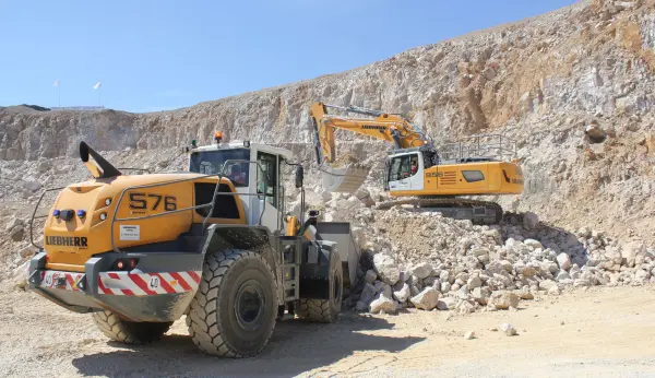
Modern high-performance top-hammer drill rigs, such as the Atlas Copco D7, can be used for both blast drilling and geotechnical works, and where the two activities are taking place together the use of this type of multi-purpose unit means that one rig can do both activities, thereby saving the client time and money compared with having to mobilize two different types of rig.
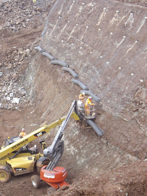
Where slopes are high or awkward to reach the use of high-production hydraulic feed beams mounted on high-reach excavators, often using umbilical controls, allows safe installations.
Drape nettings and shallow slope-stabilization facings typically use readily available hexagonal-twist wire meshes. Now, higher-angled slopes and those with less-cohesive ground conditions can be stabilized by high-tension steel meshes, such as Geobrugg’s TECCO and SPIDER meshes, sometimes replacing more expensive sprayed concrete and lacing systems respectively.
These high-tension steel meshes provide a positive active support, unlike passive un-tensioned meshes which just contain loose material after it has become dislodged. Tensioned active support meshes do not require longer-term maintenance through bleeding and reinstatement.
TECCO mesh is used on both soil and rock slopes, and owing to its high strength can reduce the number of soil nails or rock bolts, so reducing overall costs. SPIDER mesh is used to secure rock slopes that have larger unstable blocks. Both products have been fully tested by third party test houses and are now in widespread use throughout the world.
Software is also available to assist with the design of these cutting-edge systems. These programs are simple to use by a trained geotechnical designer and allow easy design adjustments on site to accommodate circumstances that may not have been fully apparent during the initial geotechnical assessment.
Should a final ‘green’ finish be required, erosion-control mattings, along with brushed-in topsoil and hydroseeding, may be used under the meshes to provide long-term, aesthetically pleasing solutions, often reducing the visual impact of the quarrying operations.
If it is intended to use rock bolts, ground anchors or soil nails close to the quarry boundary, care is needed to ensure that they do not trespass into third party properties, otherwise permission or easements will be required.
While rock bolts and, to a certain degree, ground anchors are sometimes used in quarries, especially when installed in conjunction with facing meshes, the use of soil nails is relatively new.
Soil nailing is an earth-reinforcement technique that is now widely used in the construction industry for soil slope stabilization, often instead of expensive retaining walls. Applications in the quarrying industry allow secure steep overburden slopes, not only ensuring their safety but possibly also permitting the release of reserves that would otherwise be sterilized. In one recent example where there was an unstable overburden slope, soil nailing was used to remediate it and reserves were released, which more than paid for the cost of the stabilization.
Rockfall protection
Often, the use of rock bolts, ground anchors and meshes can reduce or eliminate risks. However, it is not always practical or economic to use these owing to the face size, topography or vegetation. If there are large areas to be stabilized the cost may be prohibitive. An alternative solution may be a rockfall barrier.
On 1 February 2008 the official EU Guideline for European Technical Approval of Falling Rock Protection Kits – ETAG 027, produced by EOTA – European Organisation for Technical Approvals, became the key recognized design, test and manufacturing standard for EU countries.
Barriers in full compliance with these guidelines are now becoming available. Barriers in the range of 500kJ to 5,000 kJ will soon have official ETAs (European Technical Approvals) and the consequent CE marking. The current status may be seen at: www.eota.eu > Valid ETAs > criteria: ETA Number. At the time of writing only Geobrugg GBE barriers were officially recognized by EOTA.
The development and innovation of these new barriers means that they are notably simpler and lighter than previous designs, so are easier and quicker to install. BAM Ritchies have recently installed the first ETAG 027-generation barrier at a site in Scotland.
In order to decide on the suitability of a rockfall barrier, it is important that a full and proper assessment is made to ensure that the barrier is correctly specified and installed. Initially, the hazard needs to be understood, so that the risk may be evaluated. This is followed by the decision on the preference for face remediation or barrier installation. To design the barrier, the largest potential block size, its location and the topography of the face all need to be determined. Only then can computer simulation be carried out to determine the maximum likely impact energy and bounce height at the barrier location, thereby defining the barrier design. Installation involves staking out the barrier location and deciding on the foundations and anchorages.
The latest evolution of barriers are lightweight and easy to install, and, if long-term durability is important, high-quality corrosion protection can be provided.
Debris flows
During the course of the development and use of the latest flexible rockfall barriers, sometimes it was noted that they not only caught falling rocks but also debris flows. Debris flows typically consist of a significant number of boulders and finer material mobilized by high volumes of water.
The loadings on debris flow barrier systems comprise higher volumes but usually at lower velocities. As a result, the barriers, while appearing to be similar to rockfall barriers, are of a different design with ground anchors able to take the higher overall loadings.
The WSL organization in Switzerland, assisted by barrier manufacturer Geobrugg, has undertaken years of research and development to ensure that barriers are now designed properly and able to provide realistic mitigation. Advanced flexible debris flow barriers are now being installed worldwide; in particular in alpine countries, as well as California, Japan and Korea.
In the UK, a debris flow barrier has recently been installed in a gulley close to a landslide barrier at the Rest-and-be-Thankful pass, with the aim of preventing repeats of the circumstances that have already closed the A83 in recent years by eliminating the chance of the culvert under the road becoming choked with debris.
Landslide barriers
While rockfalls tend to involve discrete blocks falling at high velocities and debris flows tend to be associated with significant water flows that erode and entrain soil, shallow landslides generally involve lower volumes of water than debris flows and are often triggered by elevated water pressures at the rock/soil interface.
Understanding the difference between these event types is key to the provision of suitable tailored catch fences or barriers that work to deal with the type of hazard effectively and in a cost-efficient manner.
The research and development of flexible landslide barriers is now also well advanced with a good understanding of the behaviour of both the landslide material and velocities (and hence energies), and of the barriers themselves.
One of these new-generation landslide barriers was installed by BAM Ritchies earlier this year, also at the A83 Rest-and-be-Thankful, on a 35° slope with challenging overburden using deep piles and anchors. The bar and rope anchors were drilled using a rope-supported drill rig.
Monitoring and instrumentation
Development of wireless and wired communication systems, sometimes using the mobile telephone network, nowadays allows remote-sensing equipment to be installed at specific slope locations as part of ongoing monitoring solutions. Advanced laser scanning can be used to identify movements or any changes that are of concern.
New systems recently developed can include overburden movement detection, measurement of water pressure at the rock/soil interface and automated weather stations. When a system records movement, an alert can be automatically sent to the client allowing them to instigate additional protection measures or a halt to quarry activities.
Following a period of operation, the logged data can be used to correlate shallow landslide events with combinations of weather events and pore pressure behaviour, allowing an element of predictability and, thus, greater user protection and maintenance efficiency.
Conclusion
The Quarry Regulations 1999 require specific measures to be taken to ensure the stability and safety of excavations and tips. Careful planning and execution of working and residual faces can achieve this. Where the face is already in existence but cannot be stabilized by scaling or re-profiling, there are other, modern, cost-effective solutions available. These solutions continue to evolve, thus assisting compliance with the requirements.
For further information, contact David Gibson on tel: (01275) 875338; fax: (01275) 870076.