Drilling and Blasting - A view from the coalface
First published in the March 2014 issue of Quarry Management
Steve Lashley, operations supervisor for the Contract Drilling & Blasting division at Skelair International, gives a personal insight into developments in surveying techniques over the last 25 years and explains why laser surveying has now really come into its own
It is 25 years since I started in the quarrying industry. I was taken on by Ritchies Equipment, now BAM Ritchies, to produce rock-face profiles with the then new laser surveying technology. I had been a trainee land surveyor for six months after leaving the Army, so needed little training to produce the desired profiles.
The appointment was deemed necessary at the time to comply with the Quarries (Explosives) Regulations 1988, which required face profiles. While the Regulations did allow the traditional fishing-rod method to be deployed, which used a surveying rod and a measuring tape over the face, it was generally accepted that laser survey equipment was the way forward.
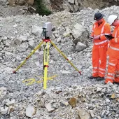
The first instrument I used was an MDL Quarryman Mk 1, which was equipped with horizontal and vertical angles and a laser range finder, and could produce either vertical-line or face-scan surveys. The software was an MDL package which, although capable of full face scans, was only used to survey a vertical line in front of the hole to give a profile. In the event of an area of weakness being identified to the side of the hole, an extra profile or two would be added.
This method served us well for a while, but we soon progressed to full face surveys using Co-ordinated Surveys’ Quarry.2 software. By this time quarries had briefed their surveyors to tie in marker boards which allowed us to make reference to and tie in with the site surveys. As a consequence, each shot hole now had a set of co-ordinates and a level. This was in the early 1990s, and the Mk 1 laser together with the probe/Boretrack and Quarry.2 software could produce surveys which, apart from taking longer, would be perfectly acceptable today. The software had the ‘burden master’ option, which would scan for weak burdens around the sides of the actual profile. Using simple trigonometry, it was possible to determine the distance between the shot hole co-ordinates and fixed points. This was particularly useful where vibration issues occurred.
The introduction of Quarry.4 made all of the above easier, and has remained the software I have used since the mid-1990s. Apart from its main purpose of producing face profiles for blasting, Quarry.4 can be used for several other purposes. For example, I have produced simple site surveys for civil engineering jobs, carried out surveys of full quarries year by year to calculate the tonnages extracted, calculated areas for meshing, and used the software and setting-out techniques to locate the co-ordinates of pre-split lines and misfired holes, and when looking for a lost probe below floor level.
As with any new technology there were sceptics when it was first launched, and for a number of years after its introduction shotfirers were still standing on the edge of faces throwing tapes over and taking face angles with clinometers to check the profiles. The depth to drill seemed to be a bone of contention, as the tape reading of the face height was preferred by some to the survey results, but unless it was done extremely carefully, the sag, slope and the bit added ‘just in case’ would invariably mean the tape made the face a good bit higher. If the floor level and the collar level have been taken at the correct points, or there is a level to work to, the laser survey results have to be more accurate. To compute the height the vertical angle and distance are used, as with a resection, so if the spread of heights on a resection is correct, and if the co-ordinates and levels of marker boards match what have been surveyed, then we can be confident that the levels are accurate.
From what I see today, laser survey results seem to be fully accepted and some quarries, where geology and design allow, are working to set bench levels, pre-drill surveys are commonplace, and laser surveying is optimizing the efficiency of the drilling and blasting operation.
Two of the most recent jobs completed by Skelair International Ltd provide an excellent illustration of how the surveying part of the job has provided the foundation for successful completion.
The first of these jobs was completed in early January for Jones Bros of Ruthin. They had been contracted by FCC Environment to install a concrete pad for composting operations at Llanddulas landfill site. To accomplish this approximately 40,000 tonnes of limestone needed to be removed. This comprised two areas in the south-west corner of the old quarry, the first of which was a short face approximately 3–6m high, and the second a nib with three sides with face heights between 5m and 9m.
The short face needed to be left at a batter of 27°, and the nib at a face angle of 11°. Working with Jones Bros’ site engineer, who had set up a GPS base station, survey control points were positioned so we could tie in our survey with his site plan and the design. The GPS was then used to gain the co-ordinates of the nearest property, so we could compute distances from the shot holes to use for the maximum instantaneous charge (MIC) from the existing regression line.
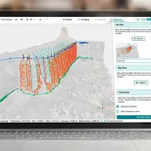
The site engineer then set out the toe line required at the short face and the crest line at the nib, and gave us spot heights above the required level along these lines. This was all that was required for us to lay out the four shots needed to do the job. Once a shot was marked out a survey was completed and tied into the site survey, the proposed level was put into Quarry.4 (see fig. 1), and the depth of each hole was displayed in the drillers report section, along with the proposed angle and azimuth. At this stage, as we had computed the distance to the nearest property, a delay pattern was worked out to ensure we would be able to stay within the parameters of the regression line. Because each shot hole had a distance we were able to vary the MIC of holes within the same shot, ie at the furthest point on one shot the MIC was 60kg, and at the nearest point on the same shot it was 48kg.
When surveying the nib, all three sides were surveyed from three set-ups. As some of the azimuths were at right angles to each other it was particularly important to see the spacing between holes at different depths, so we could charge accordingly. This was confirmed by the post-drill survey.
At the completion of this project we had succeeded in a number of areas: we managed to keep all vibration well below council limits; the final faces were at the designed angles; and the excavated depths were correct and true to the design. These outcomes were, to a large extent, due to the time taken to ensure that the blasts laid out were surveyed using the GPS to set out lines and set up survey control, and using the conventional laser survey equipment to survey the face and compute drilling angles and depths to ensure they would meet the design criteria.
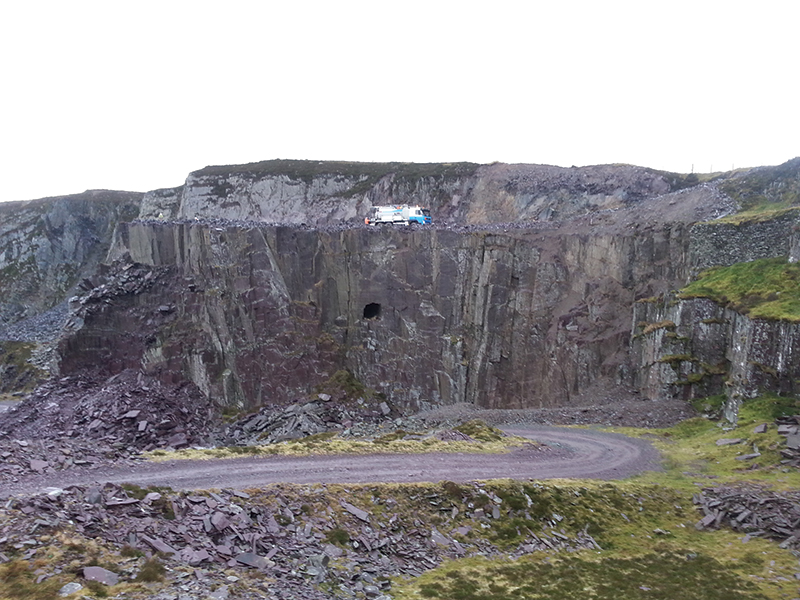
The second job was blasted towards the end of January high up in the Welsh hills. This was an old slate quarry called Alexandra, ➤ owned by CCSQ Ltd, which had not witnessed a blast since 1972. The face to be blasted was approx 30m in height and had an old tunnel running into it. It had been used in the film Tomb Raider for the character Lara Croft to abseil down, and the concrete pad where the cameras had been set was still in place.
The geotechnical assessment required that a bench should be blasted in at 15m and the final face left at an angle of 15° (the existing face was undercutting in places and at 25° in others). The top of the tunnel was at a depth of 9m and the bottom at 11m, so a detailed pre-drill survey was required. Approximately 30,000 tonnes of rock was to be blasted.
To position the tunnel we picked up the entrance to it and as far into it as the laser would reach, to give us a direction. We were then able to create points in Quarry.4, to extend the tunnel through the blast. The plan of the shot shows how the tunnel was positioned, so we could determine which holes to drill short (see figs. 2 & 3). The other holes were positioned so that where the face was vertical and undercutting the front row was drilled short, whilst the second row was drilled to full depth with bottom burdens to ensure the bench was created at 15m.
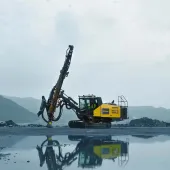
As is sometimes the case, during the post-drill survey it became apparent that deviation caused by the geological conditions had resulted some changes to what was first intended, with holes, in the main, at an angle of around 18–20° instead of the 15° on the original plan. This again highlighted the advantages we have had for the last 20-plus years, of being able to accurately measure deviating holes. Two of the holes, planned to be drilled short above the tunnel, had actually broken into it at 8.5m, thereby confirming the survey information and the assumption that the tunnel ran straight. The survey and the drilling log provided enough information to complete a comprehensive blast design, which was used to charge the shot. The results of the blast were very good, with the throw and fragmentation to the quarry’s satisfaction. The vibration level was well within the planning conditions and the resulting face looks good. Until the rock pile is dug out, however, it will not be possible to fully assess the resulting face conditions. The face before blasting and the rock pile after blasting can be seen in the accompanying photographs.
The surveying world continues move forward with new software such as Quarry.6 further enhancing speed and options, fast scanners and cloud scanners increasing the point density and thus the detail of the survey, and developments to link the laser survey with a GPS system. It will be interesting to see where the next 25 years take us, but over the last 25 years I have surveyed around 5,000 blasts and fired more than half of them, the rest being blasted by colleagues or clients, and to the best of my knowledge there have been very few problems.
I believe laser surveys have made the firing of these shots much safer and more predictable. It is the nature of rock that there will always be inconsistencies due to its composition and make up, but at least now we are in a position to know accurately how much material is in front of a hole, and from experience make a judgement as to how much explosives to put behind it.
For further information visit: www.skelair.com
In 2013, the author of this article, Steve Lashley, received the Rexnord Award for the best result in the Quarry Blasting part of The Diploma in Quarry Technology.
- Subscribe to Quarry Management, the monthly journal for the mineral products industry, to read articles before they appear on Agg-Net