Underwater Extraction Of Sand And Gravel
Nordberg Travelling Scholarship report examining current dredging methods
Thirty years ago approval for planning permission for new sand and gravel extraction sites was obtained without too much cost or effort. Easily accessible deposits, usually those above the water level, or high-quality deposits were extracted first. Planning permission for a new greenfield site is now much more difficult to obtain and, if granted, imposes stiff environmental restrictions and requires improvements to the locality. To make a site cost-effective companies have to ensure that the full potential of the site’s deposit is extracted or return to previously worked deposits using techniques and plant that are efficient for the task. Accordingly, the use of dredging as a method of underwater extraction of sand and gravel has become more commonplace in the UK.
Choosing the type of dredging plant required is not easy as no one machine will suit every type of material. The following factors need to be considered before deciding which type of dredger is most suitable:
- grading of the material, maximum and minimum size
- composition of the material, clay content etc
- compactness in situ, ability of the material to flow under water
- dredging depth
- present water depth, if applicable
- capacity (tonnes/h)
- environmental restrictions
- transportation of the material and distance between the extraction plant and processing plant
- type of downstream processing plant.
A number of different dredging systems are now available. This article describes most of these systems (draglines, backhoe excavators and submersible pumps are not included in this shortened report) for comparison purposes. These can be subdivided into two different types: mechanical and hydraulic.
MECHANICAL DREDGERS
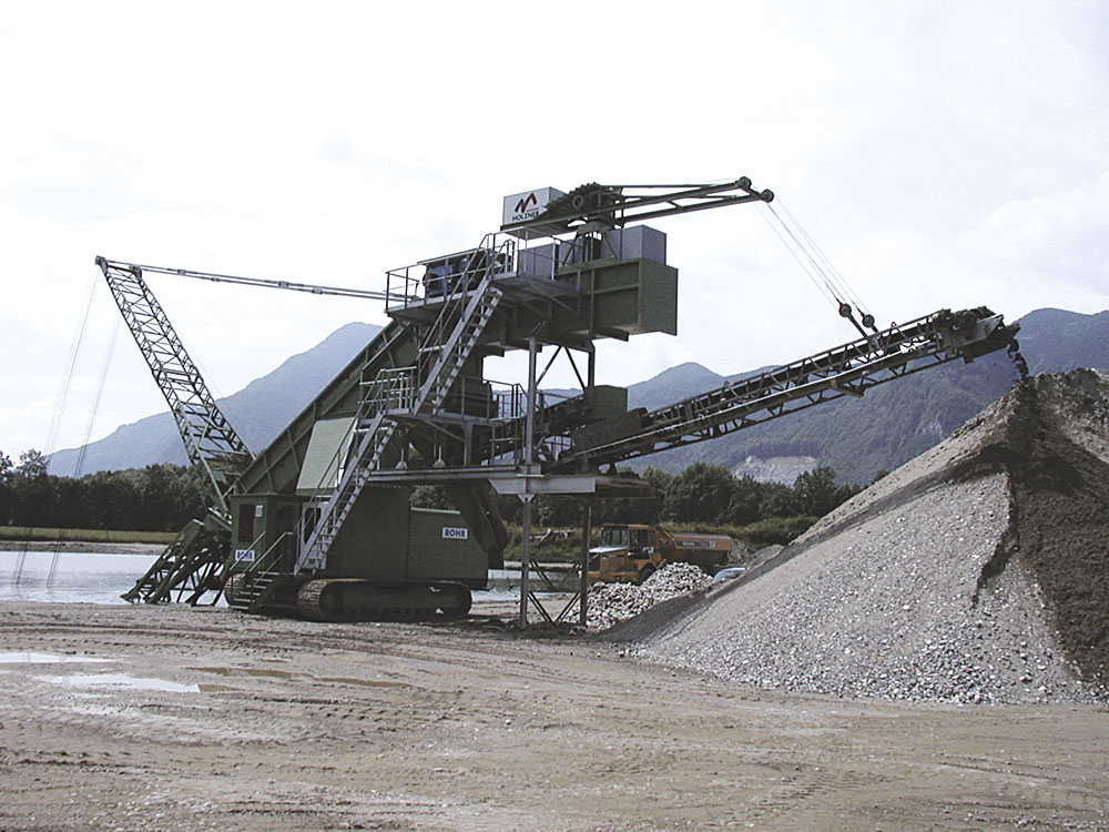
Bucket-ladder dredgers
Operating on land or water, a number of buckets are positioned evenly on a caterpillar chain or linked together to form a belt, which runs on an upper and lower tumbler supported by a dredging ladder. The ladder can be raised or lowered by winch to achieve the required dredging depth. The combined volume of the buckets and the speed of the chain determine the capacity of a bucket-ladder dredger.
Land based
On land bucket-ladder dredgers usually run on crawler tracks travelling parallel to the shore. The charged buckets travel along on the full length of the underside of the bucket ladder towards the unit and guarantee full extraction of the material. At the top tumbler the recovered material is deposited into a hopper; this can be fitted with a screen for the removal of oversize material, which is stockpiled behind the machine or fed on to a field conveyor.
Water based
On water bucket-ladder dredgers are mounted on pontoons that use winches connected to holding anchors to move around. The empty buckets travel along the underside of the bucket ladder to the bottom tumbler, while the charged buckets travel along the top side of the bucket ladder. As the buckets pass over the top tumbler they turn over and empty their contents into a chute. The empty buckets return down the underside of the ladder to begin the process again. Water-based units can dredge to depths of around 15–25m, compared with land-based versions that can only be used to depths of around 15m.
Design changes have overcome the problems of noise and wear costs, which had previously prevented the extensive use of bucket-ladder dredgers.
These machines offer the most cost-effective method of dredging but, unfortunately, are not suitable for all materials, particularly deposits with a high content of fine sand. Fine sand reduces the bucket charge as it behaves like a fluid under water and, consequently, stays level with the bucket rim (for maximum efficiency the buckets are designed to be heaped with material).
Grab dredger
Grab dredgers are mounted on floating pontoons using a boom, gantry or crane design. The extraction rate of these machines is determined by the dredging depth and the grab size.
The most popular system is the gantry design, which can be mounted on a square pontoon with a drop pool in the middle or on a catamaran-type pontoon with a drop pool to one side. The gantry is mounted on the pontoon in such a way that the drop pool and hopper are located beneath it. The grab and the frequency controlled hoist winch move along the gantry from the drop pool to the hopper and back again. The grab is dropped into the drop pool in the open position. When it reaches the material it is closed and lifted from the water. The grab then moves along the gantry and discharges its load into the hopper. If the deposit is suitable, this sequence can be operated in automatic mode, allowing the operator to clean and maintain the plant while it is running, using a remote control to stop and start the plant.
The hopper on the dredger is fitted with a grizzly. Oversize material can be tipped over the side into the previously dug area or retained for further processing. Material passing through the grizzly is usually passed over a dewatering screen with the underflow being fed to a fines recovery plant before all the material is transported off the pontoon by conveyor or barge.
In unconsolidated material, the grab digs a crater and the material flows into the void. Consolidated material can be a problem owing to the danger of high faces in the crater and the possibility of material falling on to the grab. To reduce the risk of this happening, operators working this type of material extract it in shallower cuts and then move the dredger a few meters before starting again; they return to the original position and recommence dredging only when the surrounding area is at the same depth.
Grab dredgers are designed to dredge deposits from depths of around 10m down to 100m or more, with one unit currently working in Switzerland at a depth of 180m. It should be noted, however, that the deeper the grab has to go the less production throughput can be achieved per hour, unless a double-grab system is fitted.
The advantages of the grab dredger include:
- the ability to operate in deposits containing a high proportion of large material, ie wood or stone
- low wear costs, as only the bucket is in contact with the material.
HYDRAULIC DREDGERS
Suction dredgers
There are four different types of suction dredger, all of which use the same basic design. The main difference between them is the equipment fitted at the mouth of the suction pipe to loosen the deposit.
Plain suction dredger
This type of dredger is only used for deposits that are free flowing, although it has become more commonplace for a jetting system to be used on such materials to help increase the throughput of the pump.
The pump is mounted at the rear of a steel pontoon, usually below water level to make priming easier, and can be driven by either diesel engine or electric motor. Whatever drive system is used, control of the pump speed is required to allow for difficult materials. Diesel engines are often found on dredgers but are not recommended because of the possibility of diesel or oil spillage, accessibility for fuelling, and noise considerations. Electricity is usually supplied by a cable mounted along the delivery pipe from the shore.
Most pumps used for the dredging of sand and gravel deposits are centrifugal. These lift the material, along with a percentage of water, into a rotating impeller. This applies a centrifugal force to the mixture, which is pushed out of the pump and into the discharge pipe at right angles to the direction of suction.
Suction dredgers mounted in this way can operate to a depth of 25m. For deeper operations manufacturers have placed pumps in the suction pipe below the water level. This allows dredging to be carried out to depths of 100m, depending on the deposit, although a relay pump is still required on the deck of the dredger to transport the material to shore. Deck-mounted pumps can pump up to 1km in distance, or further still if a booster pump is used.
One disadvantage of the suction dredger is that the material has to be dewatered before being processed. This usually necessitates a dewatering wheel or dewatering screen, which in turn produces a large quantity of water that requires treatment.
To move around over the deposit most suction dredgers use warping winches. There are usually three or four winches mounted on the deck of the vessel and connected to anchor points underwater or on the shore.
Suction dredger with jetting system
With this type a number of water jets are added to the suction mouth of the plain suction dredger. Water for the jets is supplied by a dedicated water pump, which sends the water down a dedicated pipe mounted piggyback on the suction pipe. The water jets not only break up weak-to-medium cohesive deposits but have also been shown to increase the extraction capacity of the main pump by 25–50%.
Cutter-head suction dredger
Cutter heads are designed for medium cohesive deposits. The hydraulically powered cutter head is mounted on the end of a suction ladder. The design and shape of the cutter head is dependent on the deposit, and a number of different versions are available.
Cutter-wheel suction dredger
Cutting wheels are designed for medium-to-strong cohesive deposits and also deposits containing a high clay content. They offer very high breakout forces, making them very efficient but more expensive to purchase and operate compared with other loosening aids. The cutter-suction dredger uses the same equipment as the plain suction dredger but the suction pipe is mounted in the middle of a suction ladder that supports one or two forward-running, hydraulically powered cutter wheels.
Jet pump
Jet pumps can be very efficient for pumping fine-to-medium coarse deposits. While the suction dredger draws sand and gravel into the pump and then out through the discharge pipe, the jet pump system uses a submersible or centrifugal water pump to force clean water, at 5–25 bar pressure, into a cast alloy mixing chamber through a specially designed nozzle. This creates a vacuum in the chamber that lifts the material through a suction duct and pushes it up the delivery pipe. The size of the mixing chamber determines the maximum size of aggregate that can be pumped. To pump large-diameter particles a large mixing chamber and nozzle would be required, making the unit quite large and impractical. It may also be advantageous to add disintegration nozzles at the end of the suction duct to fluidize the deposit, making it easier for the system to lift the material. A separate water pump is used to supply water for this purpose.
Owing to the design of the jet pump system, no moving parts come into contact with the material, although wear still affects the steel pipes and especially the nozzle and mixing chamber arrangement. It is not uncommon for these to be replaced every six months.
The working depth of a jet pump can be up to 60m, although a centrifugal booster pump is usually required at water level for onward conveying of the material.
Compared with a centrifugal pump, which can be hard to restart if the suction or delivery pipes become blocked, particularly if the pump has been left for a long time owing to a breakdown or power failure, a major advantage of the jet pump system is that sand and gravel can be left in the pipe work for long periods of time and the pump can still be restarted easily.
Pneumatic dredger
Pneumatic dredgers are based on the same principle as the jet pump, but their motive power is compressed air instead of clean water. They are designed for medium-to-coarse deposits and can handle particle sizes up to 90% of the diameter of the suction pipe.
The suction pipe is mounted vertically below the pontoon in sections to allow access to the head and to prevent material segregating in the pipe. The suction pipe comprises an internal pipe to convey the material together with an outer pipe. Compressed air is forced down the gap between the conveying pipe and the outer pipe to the suction head. Because the hydrostatic pressure of the air is less than the pressure of the surrounding water, the compressed air, together with water and sand and gravel, is pushed up the conveying pipe to the surface. This hydrostatic pressure means the dredger is not suitable for depths shallower than 12m. An increase in depth leads to a greater force being applied by the surrounding water, which in turn increases throughput and efficiency. Theoretically, there is no limit to the depth to which pneumatic dredgers can operate, although in practice it is around 90m.
At the end of the suction pipe is a hydraulically powered rotating cutter head; this is unable to apply much torque for use in cohesive or sticky deposits. Once the material has been pumped to the surface it cannot be pumped any further using a centrifugal booster pump, unlike other pumping systems mentioned. This is because of the high content of air in the mixture as well as the large quantities of solids. The mixture can be pumped directly into a barge, over a dewatering screen/dewatering wheel and then by floating conveyor to shore, or into a tank from where it is transported to shore by a pump and floating pipe work.
In contrast to other deep dredging systems, this system requires much lower capital investment. The system can be inefficient to operate, however, owing to the difficulty involved in sealing the pipe work and the expense of using compressed air as the motive power, which has approximately 10% efficiency.
AUTOMATION OF DREDGERS
Technology has advanced to the extent that most of the dredgers mentioned in this article can be fully automated. Sensors on the dredger can be connected to a PLC system that operates and monitors the entire unit. Using the PLC, the dredger can be monitored and controlled from a weighbridge or central control office, which may be a considerable distance away from the machine, while the use of CCTV cameras allows visual inspection of the dredger.
Moreover, the manufacturer can dial into the system from anywhere in the world to update files and fix problems, without a fitter having to travel to the site.
Full exploitation of the deposit can be achieved through the use of a digital model of the site, in conjunction with GPS and sonar. When the deposit depth has been reached, the dredger automatically moves on to the next point with all depths being plotted on the digital model.
This article is an abridged version of a report prepared by Clayton Forsythe through the Nordberg Travelling Scholarship 2002