Drilling For Information
Obtaining and using subsurface data to locate and evaluate potential reserves
By Dr James Tweedie, director, GeoMEM Ltd
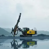
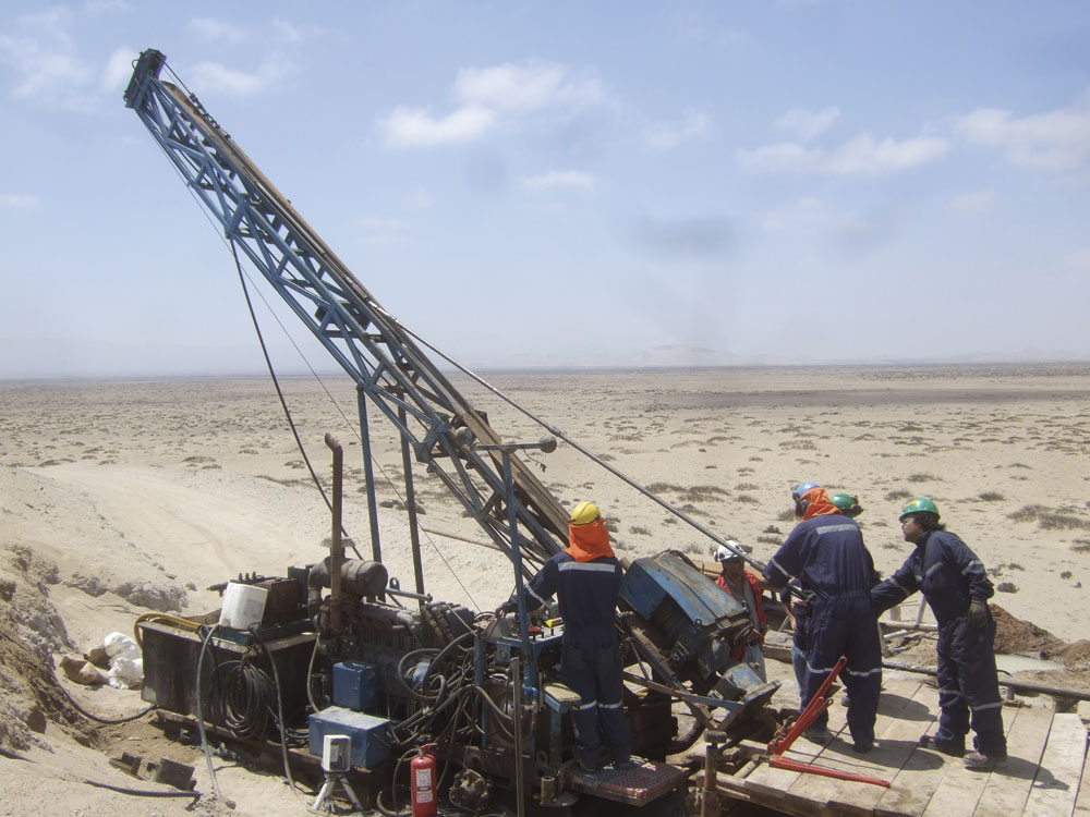
In most prospecting projects drilling for sub-surface information will be required at some stage. The borehole depths may be shallow (tens of metres) to relatively deep (100m or more). In some mining projects depths of up to 1,000m or more may be expected.
Borehole surveying is required to accurately locate resources and is considered by the author to be essential for all non-trivial holes. A trivial borehole is defined as one where it is known, with reasonable confidence, that the hole has not deviated by more than the accuracy required to locate the resource. For example, a homogenous near-surface gravel body drilled with 10m boreholes (or less) may be exempted from surveying. In this case, a deviation of 50cm at the end of the hole makes no great difference. But a series of 10m blastholes in hard rock must be surveyed to ensure safe and efficient loading and blasting.
General survey process
Borehole surveying is usually achieved by sending a probe down the hole on to which information about the direction and inclination of the probe is recorded at points down the hole. The interval between these points is usually between 3m and 10m depending on the expected bend of the hole. Smaller or larger intervals may be used if required. Some instruments require fixed distances because of their method of surveying.
The direction and inclination are derived from the original raw readings and hence the down-hole co-ordinates at the measurement points can be calculated – a process known as ‘desurveying’. From these data the path of the borehole can be displayed in 2D and 3D drawings and passed on for further processing, as needed.
In general, any borehole from which down-hole information is required should be surveyed using one of several methods and/or instruments. Today, the main survey instruments and techniques available for mineral prospecting are:
Magnetic survey instruments
Magnetic survey instruments (also known as EMS instruments) can only be used in areas that are largely unaffected by magnetic anomalies – both natural and man-made. As the name suggests, magnetic survey instruments use magnetometers to obtain the probe’s direction (similar to a compass) and inclinometers or accelerometers to obtain the inclination (using gravity).
These instruments cannot be used in magnetic casings or drill rods, or in magnetic rock. Where they can be used they are generally fast, reliable and of lower cost than other methods. They are generally short – the actual probe being about 1m in length.
Currently available EMS instruments include:
- Combo and Peewee systems from Devico (Norway).
- EZ-Trak and AQ from Reflex Instruments (Australia).
- MI3 from Icefield Tools (Canada).
- PathFinder series from GlobalTech (Australia).
- Ranger Explorer series from Ranger Surveys (Australia).
- MagCruiser series from Stockholm Precision Tools (Sweden).
There are many EMS instruments to choose from and deciding on which one to use will be based on factors such as availability, cost and accuracy. In most cases local representatives will be on hand and renting options will be available, as well as outright purchase.
Non-magnetic survey instruments
There are two main methods of surveying in a magnetic environment. At present, both usually incorporate inclinometers or accelerometers to gather inclination data but use very different methods to obtain the azimuth or direction of the probe.
Differential direction method
Like the magnetic method, the survey is carried out as a series of discrete measurement stations down the hole. The starting azimuth must be measured to a high level of accuracy and then the direction differences (hence ‘differential’) for each station are added to the direction of the preceding station. This requires good operational practice to avoid a build-up of systematic errors.
Experienced operators can achieve very good results with this method. Some examples of differential survey tools include: the DeviFlex from Devico, which uses strain gauges to determine any bend in the tool; and the Reflex Maxibor, which uses an optical system to determine bend. Both examples are fairly long tools (3m or more) to allow enough distance to determine bend.
Gyroscopic or inertial navigation methods
There are various types of gyroscope-based systems available at present. These use either mechanical gyros or miniature electromechanical system (MEMS) gyros. The probe continuously detects its path of movement in three dimensions, and from this data are extracted to produce the required angles (inclination and azimuth) at points down the hole and thus calculate the 3D co-ordinates. Because gyro systems record continuously, it is also possible to generate a continuous track of the borehole path.
Of particular use is a north-seeking system which can find the Earth’s north and actual inclination, and thereby maintain accurate in-hole positioning. North-seeking systems use the Earth’s rotation to define true north and, in effect, replace the functionality of magnetic sensors. Gyro systems without north-seeking capabilities must have an accurately surveyed start azimuth, with the down-hole direction values calculated using the differential method described above.
However, gyro system costs tend to be considerably higher than the other methods and operational requirements may be more complex (a greater operator knowledge of the technique is required). Hopefully, this will change as the MEMS technology matures and becomes more widely used.
The Reflex Gyro, FlexIT HTGS and Icefield GyroShot are examples of start azimuth/differential systems, while the FlexIT Target INS and SPT Gyro Tracer are examples of slimline systems using north-seeking technology.
The survey method is largely dictated by the surrounding rock types, end requirements and budget. The budget should, arguably, be the lesser influence, as basing a final plan on incorrectly located data can cost considerably more than a slightly larger drilling budget.
Directional drilling and surveying
In addition to borehole surveying, directional drilling – where the direction of the hole is controlled and, therefore, hits the intended target – can provide considerable advantages and cost savings in certain projects, especially in deep drilling and sensitive environments. Multiple ‘child’ holes can be branched off a main hole and controlled to further targets. This means there is a single surface location for the drill rig, no rig movement and less impact on surface environment, with resulting savings in drilling and surveying time. Several companies offer directional drilling services, including Devico in Norway.
Using the data
Once the borehole surveys have been completed other information gathered from the borehole (such as lithology, structure, mineralization, geophysics, photographs and geotechnical data) can be located as accurately as possible in 3D and, hence, provide accurate sub-surface models.
By obtaining the best-possible survey data coupled with the best observational and other quantitative data, a solid foundation of original raw data is created upon which to build further processing, interpretation and modelling. If the raw data is bad there is no way of correcting it with any confidence using software – later processing may paper over the cracks, but they will still be there.
Initially, borehole information is usually combined in a descriptive borehole (graphic) log and there are many good software packages available that offer quick log production. In some smaller projects, the output of these applications may be the required end product, but for most prospecting/exploration further work is required of the data.
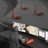
The next stage is to obtain the best-possible knowledge of the sub-surface ‘situation’. Borehole data can be used in various software packages to produce fence diagrams, cross-sections and 3D visualization images based on interpolation (under a geologist’s control) between the boreholes. However, it is always important to be aware that the impressive diagrams that the software has produced are ‘artefacts’ based on the interpolation methods, assumptions and controls made by the operating geologist.
During a drilling project these results may indicate:
- Areas requiring boreholes to infill a drill pattern for more subsurface data (these may be from the surface or branches from, or extensions to, existing boreholes).
- Extensions of the drilling area to cover subsurface continuations that have not been ‘closed off’ by the current drilling.
- Use of hole-to-hole or surface-to-hole geophysics to help define subsurface bodies or structures.
- The next stage may be reserve evaluation and extraction planning/design – and, again, there is a range of software to cover this area. Using all the data, it is possible to plan and design the quarry or mine (or extend existing workings) and there are several well-established and time-served systems for this, such as: RockWorks, Datamine, Gemcom, Micromine, Strata Explorer and Geotic.
RockWorks from Rockware (Colorado, US) is a long-established system that first appeared in the mid-1980s. It is a low-cost system that takes the user from original mapping and surface data collection through drilling and borehole logging to reserve estimation and 3D quarry modelling as well as simple mine working and pit models. This may be all that is needed by some companies; it offers a complete set of geological utilities and options for other areas including environment, geotechnical and petroleum.
Datamine (now part of CAE Mining) has been around since the early 1980s and, under CAE Mining, consists of a series of modules covering aspects of: exploration/field data capture/ drilling/ borehole logging; resource modelling; mine planning; and mine scheduling and production. Specific modules are purchased as needed throughout the life of the project.
Gemcom (including Surpac and Whittle) provides modules and system, covering applications from initial geological exploration/field data capture through drilling/borehole logging to mine/quarry planning and scheduling. Some modules or systems are targeted to more specialized areas, such as coal/stratified deposits and block caving. As with the previous two systems, the first Gemcom systems appeared in the 1980s.
Micromine appeared in 1986 and offers a number of solutions for field data capture, exploration and mining with mine production (control and management).
Strata Explorer from GAEA Technologies Ltd (Canada) evolved from a simple system of borehole logging and cross-section software and now offers borehole data-management and 3D-view capabilities.
Geotic has recently appeared from Canada and offers software ranging from log production to 3D modelling.
All these systems will take 3D data produced in the exploration phases to produce 2D and 3D models upon which to base further decisions – whether extending the project or moving to production quarrying/mining. Apart from Geotic, all have a well-established history having been ‘born’ in the original heyday of computer-based exploration and mining software in the early-to-mid-1980s. They are mentioned here to indicate the wide range of software tools and systems currently available as an aid to prospecting and surveying.
For further information visit: www.geomem.com