Maximizing The Potential
How process automation and instrumentation can improve safety and efficiency
The author, Carl Pinches, is industry marketing manager (mining, aggregate and cement) with Siemens Process Automation
The quarrying industry appears to be moving towards the standards and practises seen for many years within the chemical industry. It is important, however, to see these two market segments as markedly different regarding the drivers for automation and indeed the expectation for performance. It is not possible to simply superimpose the chemical industry’s automation practises on to the quarrying industry and expect a seamless step to improvement in both safety and efficiency.
The need for increased levels of automation in quarrying has not simply materialized but has its roots in the more basic industry trends seen over recent years, for example:
- industry consolidation
- higher accuracy/quality demands
- environmental regulations
- increasing production costs
- decreasing product sales value
- reduced in-house engineering/support expertize.
Industry consolidation is by far the main catalyst for the growth in demand for automation seen today; witness the current race by global companies to acquire smaller or independent quarrying companies. Their need to gain an immediate return on investment through plant optimization and efficiency has accelerated the automation need beyond the natural evolution process. The chemical industry can show the correct way to go for the future, but it does not have the same roots in history as the quarrying industry.
Process automation systems
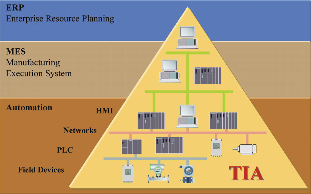
Process automation systems come in many different forms but there is a generic architecture that most will follow (fig. 1). The most common levels used are:
- management reporting/data storage
- operator/engineering work- stations (DCS/SCADA/HMI)
- networks
- controllers (typically PLCs)
- field instruments/field devices (variable-speed drives, instruments, motor controllers, MCCs, analysers)
Critically, information flows bi-directionally between each level of the automation pyramid. The more integrated the different elements of the control system are, the more effective the whole system will become. Today, Siemens have a totally integrated automation (TIA) strategy. This allows fully integrated asset management from the top management-reporting level down to, and including, the field instruments/devices. To realize this kind of benefit the field devices must be considered a full part of the control system. In reality this is not the case; field instruments/devices often become an afterthought to the automation system decision process.
Ultimately, this dramatically limits the benefits that can be realized from the investment in process automation.
Process instrumentation
The physical measurement of a process variable is the most critical element of any control system. This is the ‘link’ between the real world of the quarrying process and the digital world of the control system.
Instrumentation is almost always seen as the least significant part of any complete automation system. Indeed, it is not unusual for a new control system to be bolted on top of existing instrumentation that can be over 10 years old.
The most common methodology used within the quarrying industry to link instrumentation to a control system is the 4–20mA analogue loop. This is acceptable for reading the primary process variable but provides very little else. The 4–20mA analogue loop has its roots in the original analogue technologies used when electronic instrumentation was first commercially available in the late 1960s. In today’s ‘digital era’ almost every element of people’s lives is touched by microprocessors, from the watches worn on their wrists to the cars that they drive. When it comes to reading complex measurements within quarries, however, horizons are limited as the industry stays with tried and tested analogue communications.
Instruments today are invariably microprocessor based, even if the output is analogue (fig. 2). The instrument will take a physical analogue measurement, such as pressure, and immediately convert this, through an A to D converter (analogue to digital), to a digital equivalent. The information is then processed digitally and displayed on the instrument digital display. The signal is then converted back to an analogue signal, through a D to A converter (digital to analogue), for transmission to the control system on the 4–20mA loop. Once received by the control system the analogue 4–20mA is converted back to digital through yet another A to D converter.
If instrumentation with digital communications is utilized, the process will be greatly simplified. The instrument will still take an analogue physical measurement and immediately convert this, through an A to D converter, into a digital equivalent. Once in a digital format, however, it remains in this form even when transmitted into the control system. Every time a signal is converted from A to D or D to A the possibility for the introduction of errors is increased.
A basic example of how digital communications can help the user is the not uncommon experience of having an instrument reading 8.2bar in the field and the control system displaying 8.9bar in the control room. This can be avoided by using digital communications as the conversion is done only once in the instrument, not independently by both the instrument and the control system, as with analogue transmissions. This completely removes the need for time-consuming loop testing, which needs to be done regularly to ensure the reliability of information.
Once the move to digital communications has been taken there is also the opportunity to improve plant automation. Instrumentation today is ‘intelligent’; it will measure numerous process variables and self-monitor its own condition. An analogue 4–20mA loop only shows one primary process variable, eg level, pressure, flow, temperature. Digital communications, however, allow users to utilize every piece of information available within the instrument.
An example of this is the use of valve positioners in conjunction with electric/pneumatic actuators to control the position of a valve, ie fully open, fully closed or part open (to 60% for example) (fig. 3). To do this with an analogue system would typically require three twisted-pair cables to each positioner — pair 1 from the control system for the set-point value, pair 2 to report back the actual valve position variable, and pair 3 to indicate that the valve is actually shut. In total this requires two analogue channels and one digital input in the control system per valve positioner.
By using digital communications only one two-core cable is required. The set point can be sent to the valve and the actual position fed back on the same cable. In addition, any confirmation signal for valve ‘closed’ can also be sent back on the same cable. The reduction in cabling and I/O required is the obvious gain, but the following information can also be achieved at no extra cost:
- valve-stroke counter exceeded
- hours in service
- change in valve-stroke time
- change in valve seat position
- parameter change notification
- valve in ‘hand’ operation.
Valve wear can be assessed by the positioner rather than by maintenance personnel during regular plant inspection. If there are a number of valves on site they can be serviced based on the number of valve-stroke operations they perform rather than by time; the most used valves being serviced more regularly than those used infrequently. The wear on a valve seat can be shown by the positioner indicating that it is travelling further to shut the valve. The increase in time taken to close a valve when compared to the initial commissioning closing time could indicate wear or an obstruction within the valve. All of these parameters allow a quarry to use its limited maintenance resources effectively and prioritize where they are used.
Field device commissioning
The quarrying process typically requires upwards of 200 points of process measurement, many of which will be supplied by multiple instrumentation suppliers. Commissioning of instrumentation is a real problem for on-site engineers due to the multitude of manufacturers and product-specific software required for commissioning. Utilizing a site-standard communications protocol, such as Profibus, offers a whole new approach to instrument commissioning. SIMATIC PDM (process device manager) is the generic commissioning tool offered by Siemens for Profibus networks.
SIMATIC PDM is a consistent, manufacturer-independent software tool for the operation, configuration, parameterization, maintenance and diagnosis of intelligent field instrumentation based on the EDD (electronic device description) standard. It can be used independently of a specific automation system via a PC or as an integral part of Siemens’ process-automation system, the SIMATIC PCS7.
The following core functions of SIMATIC PDM allow users to keep all instruments and automation processes under control:
- set-up and modification of parameters
- comparison
- plausibility checks
- data management
- commissioning functions.
Generic commissioning tools are not new. Most installers will be familiar with HART protocol devices, which allow a digital signal to be imposed on the 4–20mA analogue output to provide digital communication capability. This protocol had been widely adopted in the chemical industry to allow remote commissioning of field units, typically within hazardous areas. This has now been largely superseded by more advanced digital Fieldbus systems.
PDM differs in that it is a fully integrated software package that is not limited to commissioning and parameterization of field devices. It is important to stress that the PDM package is non-vendor-specific. There are more than 1,000 individual products from over 100 manufacturers included in the product library. This is continuously expanding and any new additions are available free of charge as Internet downloads. PDM offers one ‘look and feel’ for instrument set-up, regardless of instrument type or supplier. HART-DDL remains a widely accepted standard and is strongly supported by device manufacturers. To ensure PDM remains compatible with existing instruments any HART device is automatically included in the SIMATIC PDM library.
Field instruments can be interrogated with a direct one-to-one connection from a PC to an individual instrument; this would typically be used by maintenance specialists to have units pre-programmed and ready to install. The more common approach is to embed PDM within the control system. Once a fault is indicated on the operator’s workstation, the instrument in question can be interrogated to display the complete operating parameters and diagnostic information, allowing the reason behind the fault to be established. This negates the need for exploratory work in the field as the fault can be displayed on the operator’s workstation. Maintenance staff can then be directed to the specific fault fully prepared to rectify the situation quickly.
Configuration parameters between manufacturers are now becoming standardized. Fully integrated Profibus devices (profile 3.0), regardless of manufacturer, can be ‘hot swapped’ in the field. This provides the end-user with the flexibility to pick and choose the manufacturer they prefer. All the data from the original instrument is archived and can be downloaded to the replacement device without the need for user intervention.
Integrated asset management allows traceability of the equipment and processes. Automatic records can be maintained of who changed what and when, again without the need for human intervention. If an item of equipment needs to be maintained or calibrated regularly to remain within tolerance, a full history of that equipment can be viewed and analysed. This can prove invaluable for meeting current environmental regulations. For example, keeping records of water quality and discharge quantities is not uncommon in industry. Being able to validate and prove the accuracy of the readings, however, will soon become as important as the recorded discharge information itself.
Conclusion
Through a fully integrated approach to automation systems many of the needs generated by the trends in quarrying can be encompassed in one overall solution. A new top-down approach to plant, equipment, process and reporting needs is required. If the issues are only solved gradually, potentially more time will be expended while achieving less and invariably duplicating effort.
The quarrying industry is in a position where it can learn from other highly regulated industries. Proven technology exists today that can make people’s lives easier, while meeting the required expectations. There is little risk associated with implement-ing integrated automation but the financial gains can be significant.