Powered Up
The growing use of high-powered drives in the cement industry
Adapted from an article by Dr Ralf Briest and Conrad Friedrich of Helmke, an AEMT member
In today’s industrial environment, the three-phase induction motor has become the most common drive source for most applications. Small and medium-power motors are more often than not standard ‘off-the-shelf’ designs, however larger motors with high power ratings are much more specific with regard to their mechanical construction, as well as the electrical parameters to make them suitable for their application and operating conditions.
High-power motors are often bespoke and custom designed, and every detail has to be carefully planned and implemented. A large motor is not just another electrical device among the many others. Thorough testing of a high-voltage motor before installation can ensure that the planned and required parameters are achieved before it is installed into the plant. This reduces the risks, ensures that schedules are met, and keeps any costs to a minimum.
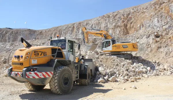
The selection and dimensions of a drive are determined not only by the power requirement, but also by the start-up needs. Crusher drives typically require a high-power and high-torque machine. This is also a main consideration with drives for mills and kilns. They both require large amounts of power when starting and an initial starting torque up to two-and-a-half times higher than the nominal torque. These plants may have to be started when filled to capacity and at maximum load; this can occur after an emergency stop takes place without the normal co-ordinated shutdown routine.
Running these drives continuously means that they are permanently exposed to high vibrations and large load fluctuations. It requires a strong design to endure fatigue in both the electrical components of the motor as well as the mechanical assemblies, especially in the area of the bearings and end shields. Alongside these electromechanical considerations, specific environmental conditions have to be taken into account. In some industries, such as cement, the dust loading is disproportionately high and significantly reduces heat dissipation. In other plants the dust could be hazardous and require an Atex motor to minimize the explosion risk. By causing overheating, dust can make a machine less efficient and damage or significantly shorten the life of the electrical insulation. Proper maintenance of the bearing lubrication under these conditions is particularly important for reliable operation and to ensure that the expected life is not reduced.
If dust deposits accumulate and bond on to the rotor the machine can become unbalanced, resulting in increased vibration and additional mechanical stresses. Vibration monitoring should be conducted regularly and the machine’s temperature should be monitored to avoid premature failures.
A regular maintenance programme should take into account the operating and environmental conditions, as well as the type of motor to maintain the original performance of the machine. This will help to avoid critical failures and expensive downtime.
The high starting torque required in a mill or a kiln considerably limits the choice of drive system. Over-sizing is neither technically nor economically reasonable and should be avoided as far as possible, especially in the power range up to 10MW.
The squirrel-cage induction motor has a simple and robust design which is very well suited to most mechanical and environmental requirements. In addition to its low maintenance costs, this type of motor is very reliable. However, the torque requirements for direct on-line starting, and the necessarily high nominal torque, will never be met, even with a specially developed motor design. At the same time, the starting current and its duration will often exceed the operational mains values. Besides the high starting torque, there is a considerable centrifugal mass that has to be activated, which can further increase the start-up time (fig. 1a).
To overcome this problem an induction motor with slip rings can offer three times the starting torque, if it is used in conjunction with an appropriately designed starter. In larger motors the starting torque of a slip-ring motor can typically be double. However, slip-ring motors and their compatible starter are a costly design. They are also associated with high energy losses during start-up (fig 1b).
The use of the squirrel-cage design in conjunction with frequency converters is less expensive and is now used for high and very high power ratings. A change of the stator frequency allows operation in the low-slip area, which is less than the breakdown slip. This results in minimal losses at each operation point, as well as during the starting period. In the range of low slip between zero and breakdown slip, the motor is able to achieve a torque up to its maximum value – the breakdown torque. This is always a lot larger than the nominal torque of a motor. This situation can be employed for a short time within the motor’s thermal limits without problems.
In the industrial sector variable-speed drives are more common and are replacing other systems in process automation. Not only is the operating performance during the start-up phase eased, but due to the freely adjustable and continuous operating range, process controls can be optimized and achieve vastly improved efficiency.
Due to the adaptability of the drive to the working machine, the ideal speed can be used at each operating point. The technological process can be optimized and the whole system operated with minimal losses. This saves energy and will often more than compensate for the additional cost of upgrading an existing system (fig. 1c).
When Helmke received a request for a main cement factory mill drive, the electrical system for the mill consisted of an input rectifier transformer, dc link frequency inverter and a three-phase squirrel-cage motor. The complete system needed to be designed and installed taking into account a very high starting, or initial breakaway torque, of 1.7 times the nominal torque of the motor for a period of at least 10s.
The requirement was for speed variance at constant torque for the full range up to 700 rev/min, and up to 1,480 rev/min at the nominal power of 1,700kW (10,800Nm). The very high start-up torque, in addition to the speed variability, made the use of a frequency converter essential (see fig. 4). High operational reliability and very low circuit feedbacks were further design considerations.
A dry-type input rectifier transformer was chosen, which represented the best solution under the given environmental and installation conditions (see fig. 2). In addition to the adjustment of the input voltage from the mains to the input voltage of the frequency converter, the transformer generated the phase shifts necessary for rectifiers of pulse count 12 and above, and acted as a disproportionately large commutation inductance.
The design had only slight system variations and distortions of the current and a reliable connection to most mains systems was possible. The frequency converter consists of several switch cabinets with a nominal power of 2300kVA to optimize the motor’s requirements. It was positioned in a relatively clean environment not far from the motor. The control system was able to handle operations from standstill, so that the high starting torque could be provided for the very slow-starting mill, without any restrictions during the start-up phase over a prolonged period.
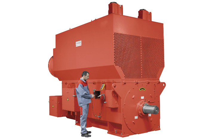
The motor itself was a three-phase squirrel-cage asynchronous induction motor with a capacity of 2,000kW. It is able to meet the specifically required conditions during starting. Special sleeve bearings absorb the high bearing forces and dynamic bearing load, as well as offering long durability. The difficult environmental conditions are kept away from the interior of the motor by an air-to-air cooler, which prevents possible damage to the internal electrical insulation and the mechanical mounting. It also reduces the risk of the rotor becoming unbalanced during operation.
When designing a highly optimized and cost-effective drive solution, there is always a risk that the operating parameters at the limits of the entire system can only be estimated, and the complex interactions of the work machine and drive are often not fully known at the initial stages. Full testing of the complete system overcomes this should be carried out before installation, to ensure a trouble-free interaction of the components (see fig. 3).
Power drive systems now typically favour variable-speed drives. They simplify the technological processes and provide a significant improvement in system efficiency. On the other hand, they also allow the integration of a wider range of parameters into a very efficient system design.
The advantages of using frequency converters compared with conventional constant-speed drives has made possible the solving of problems of increasing complexity. Bespoke drive applications of various power ratings are now being created which contribute to highly cost-effective and energy-efficient process systems.