The Challenges of Designing Gearboxes for the Extractives Industry
First published in the June 2015 issue of Quarry Management as Gearing Up
Selecting the correct design of gearbox for an application can be a crucial decision that will affect performance, efficiency, reliability and cost. Having a good understanding of the basic principles and suitable applications is, therefore, essential. Dave Brown, sales manager for Brevini, offers some technical guidance
Gears have been in use since the times of Archimedes and Aristotle, and they continue to play an essential role in mechanical systems across the world. While the basic principles remain the same, the technology has advanced considerably with different gear arrangements offering a variety of benefits for the right application.
A gearbox is most commonly designed to provide a reduction in speed from a prime mover (eg electric motor) and deliver the necessary speed and torque for a particular application. The gear ratio is the relationship between input and output speed, with output always defined as unity.
For example, for an electric motor prime mover with a speed of 1,500 rev/min and a driven machine at 500 rev/min, the ratio is as follows:
Input:Output or 1500:500 = 3.00:1
In simple terms, three revolutions of the input shaft will produce one revolution of the output shaft. Gearboxes may use a variety of gear arrangements in order to achieve the desired output in terms of speed, torque, efficiency, size, noise, service life and maintenance requirements. The type of gear arrangement is defined by the design of the gear teeth and how they mesh together.
Straight-cut gears
The most basic type is the spur or straight-cut gear, which has teeth that are parallel to the axis of rotation. This design offers economical performance and is equally good for both high- and low-ratio applications. The spur gear can also be used in combination or multiple stages, to achieve high gear ratios.
However, the straight-cut design means that the point at which the gears mesh occurs along one tooth at a time, which can cause increased wear and noise – especially at higher speeds. The noise is caused by the single point of contact between the drive and driven gears at the start of gear mesh. This is in contrast to the rolling or sliding type of contact associated with other gear technologies.
A refinement of the spur gear is to slant the teeth in relation to the axis of rotation, which allows a more gradual engagement of the meshing teeth for multiple teeth to be engaged simultaneously. This provides a smoother motion with reduced noise. Furthermore, the design has a greater tooth contact area which increases the amount of torque that can be transmitted by 10-15%, while still maintaining very good efficiency.
However, the design of a helical gear induces axial thrust in the gearbox which should be accommodated by installing thrust bearings or changing the gear design to incorporate twin helix stages, which will counteract the axial forces, or a more complicated double-helix gear. This is a gear with the teeth set in a herringbone arrangement – but the design is more complicated to manufacture, as well as to assemble and so will carry a price premium compared with the spur gear.
Bevel gear arrangements
So far the gear arrangements have transmitted power in parallel axes, but a common requirement is to redirect the rotational axis by 90°, which usually involves bevel gear sets or worm drives. The latter have seen significant improvements in efficiency, especially for reduced-torque applications at lower ratios and they still represent good cost efficiency in some applications.
The orientation of the teeth in bevel gear sets can be straight cut, but the more common style is a spiral-cut gear which offers reduced noise levels and greater efficiency. The most common are Gleason or Klingenberg and in terms of costs, the spiral bevel gear option becomes more attractive when the application requires more than 7.5kW with a ratio above 20:1.
Planetary designs
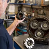
The final group of gear arrangements is the planetary gearbox which takes its name from the normal gear arrangement consisting of a central sun gear, orbiting planet gears and outer ring gear/annulus.
By splitting the loads through multiple contacts between the planet gears – typically three – the torque capacity of a planetary gearbox is very favourable against other solutions. Additionally, the symmetry of the design means that most of the gear separation loads associated with other solutions are self-cancelling in the planetary design. These factors combined mean that the planetary solution can be significantly more compact and cost-effective in many applications.
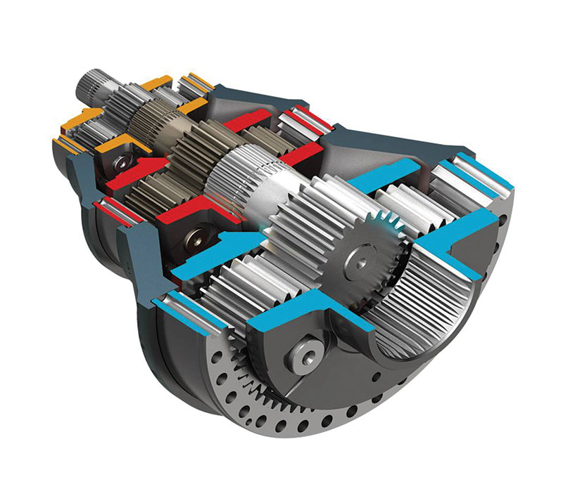
The benefits of the planetary gearbox can be combined with a bevel or helical gear system, offering the benefits of both designs. This allows the advantages and benefits of the different technologies to be combined to optimize the solution for the demands of a specific application. The gearbox design is common in many of the heavier industries where reliability, efficiency and total cost of ownership are important factors.
Crucial duty cycles
Many factors influence the design of a gearbox for a particular application. The key is determining as many of the crucial factors as possible before the selection process begins.
Specific information regarding the reduction ratios, input speed and torque are critical. However, it is also important to define the real duty cycle for the equipment, defining frequency and details of the start/stops, variations in the running torque and speed etc. Only with a full duty cycle can operators accurately select and design a solution that will perform for the required life of the machine.
The location of the application is also critical, as the design may have to consider ambient and environmental conditions, space requirements, mounting arrangements, weight, noise and maintenance requirements. In addition, the backlash, which is the space between two meshing gears, may need to be specified for particular applications. Every gearbox will have some backlash designed into it, to allow lubrication of the gears and prevent the gearbox from locking up.
Finally, there are the more specific design characteristics such as shaft alignment, efficiency and expected lifespan, which can influence certain design choices. Gaining a basic understanding of the more common gearbox designs, it is possible to appreciate the alternatives for a particular application.
The next step is to discuss more specific requirements with design engineers who specialize in this field. Brevini have always used experienced technical sales engineers to assess each unique application to offer advice and technical knowledge in order to help customers define the correct gearbox for every application.
For more information visit: www.brevini.co.uk
The challenges of designing gearboxes
The use of planetary gearboxes is widespread due to their compact design and ability to provide high torque output in various applications while delivering good energy-efficient performance.
Most manufacturers will offer in-line and right-angle designs but there needs to be a range of sizes to ensure that each application is fitted with the most suitable configuration without adding unnecessary weight or bulk. Brevini say their S Series planetary units offer a good example of the benefits this technology can bring, delivering 60% more power (nominal output torque up to 5,000KNm) than traditional gearboxes of the same size.
Any minerals that have been quarried require transportation and processing, both of which are continuous operations that need robust, high-power output, versatile gearboxes to ensure the process is uninterrupted. The most common choice is a helical or bevel-helical gearbox which can be constructed to suit each item of equipment complete with a range of options to meet a wide variety of applications.
An example of this design is the Posired 2 range from Brevini, which is available in a modular format in 25 sizes with a nominal output torque up to 1,000kNm. As a very adaptable product, it can be used to replace existing, end-of-service equipment without making alterations to the existing structure. In most cases the new gearbox will provide additional capacity as well as new features without affecting the overall size and weight of the base equipment.
In addition to mineral processing equipment, there is self-propelled machinery that requires equally robust and reliable drive systems to suit the demands placed on these machines. In equipment that requires wheel drive or track drive units, a compact design is crucial to maintain the plant efficiency, while ease of maintenance is important in the day-to-day running.
Track drives are required to fit inside the drive sprocket of the machine and, as such, must be capable of providing reliable and efficient service. Not only must they be compact in design, but also capable of having features, including brakes and disconnect devices, to allow a vehicle to be towed.
The working conditions of such drives can be very harsh so they must be engineered with suitable reductions for the applied load and with appropriately specified sealing to withstand mineral processing conditions.
- Subscribe to Quarry Management, the monthly journal for the mineral products industry, to read articles before they appear on Agg-Net.com