Appearances can be Deceptive
Never judge a load-cell by its cover
Strain gauge load-cells are the life blood of modern, high-performance industrial weighing systems, playing a particularly important role in weighbridge systems. Despite the harsh operational environments weighbridges encounter (extreme temperatures, ice, snow, wash-down, flooding, excessive braking and minimum maintenance), the load-cells are expected to provide exceptional reliability and accuracy.
When Arthur Lincoln Thurston patented the first compact compression strain gauge load-cell in 1949, little did he know that this humble invention would continue to be at the heart of industrial weighing more than 70 years later. Modern units have come a long way since then, but the basic technology and overriding sound mechanical design-build principles established by Thurston are still vitally important.
One fact is clear. There are no quick and easy ways to produce high-quality weighbridge load-cells. Unfortunately, there are always companies who will try to make a product cheaper by cutting corners – even though quality will suffer. Short-circuiting any of the fundamental principles or processes will result in inferior-quality load-cells. As a result, low-cost weighbridge load-cells are unlikely to meet all performance criteria and will almost certainly turn out to have a higher cost of ownership in the long term.
Unfortunately, low-cost, low-quality load-cells have entered the market from unscrupulous manufacturers and some weighbridge companies are happy to try to capitalize on this. At first glance, these inferior load-cells may look the same as their high-quality counterparts from the outside, but there the similarity ends. Often the problem stems from the fact that some load-cell manufacturers produce a ‘golden load-cell’ for weights and measures evaluation, which is not typical of the quality of normal production-run load-cells. Indeed, this evaluation load-cell may not have been manufactured at the same site as normal production load-cells (VCAP has been established to try to bring greater control to load-cell manufacture).
The losers in all this are the end-users, but they are often oblivious to the consequences, believing the ‘false’ performance claims of the weighbridge supplier. More often than not, the user may not be aware that inaccurate weighing is costing them money as well as risking their reputation with their customers.
The following key factors are vital to ensure manufacturers produce high-capacity load-cells that consistently meet the required performance and reliability criteria:
- Sound mechanical design principles including optimized environmental sealing.
- Repeatable, high-specification material properties and heat treatment for the critical load-cell structural components.
- High-quality strain gauges designed specifically for the load-cell measuring element.
- Well disciplined manufacturing and testing procedures.
- 100% product testing.
Mechanical design
The mechanical design criteria for a load-cell are of paramount importance. Testing and compensation procedures can only fine-trim performance characteristics, therefore the original design must take into account real working environments. The design should ensure the load-cell has good tolerance to off-axis, side and angular loading. Good environmental sealing is vitally important to prevent premature failure, especially with regard to cable entry.
Material specification
Load-cells are very-low-deflection springs that must behave in a highly repeatable manner as they are loaded and unloaded. As a result, optimized material selection and heat treatment for the measuring element and other key components play a critical role in this.
Strain gauges
The matching of strain gauge characteristics to those of the load-measuring element is crucial, especially where creep and linearity characteristics are concerned. The performance of the finished load-cell is also directly dependent on the repeatable nature of the strain gauge bonding process.
Testing
Load-cells have individual characteristics and, therefore, each and every load-cell should be tested and compensated during the manufacturing process. It is often in this area that lower-quality manufacturers cut corners to reduce costs. Testing must include load cycling and temperature testing.
Design concept
There are three fundamental load-cell designs used in modern weighbridges:
- Single-ended beam cells
- Double-ended beam cells
- Canister
Single-ended beams
Cumbersome, high-capacity, single-ended bending-beam load-cells represent outdated technology and are far from ideal for weighbridges. Typically, they have only four strain gauges and are susceptible to torsional, off-axis and side-loading effects. Mounting assemblies and fasteners are subjected to high forces as load is applied to the cantilever beam. Design performance limitations usually restrict construction to alloy steel rather than stainless steel, and ensuring effective environmental sealing can also present a problem.
Double-ended beams
Double-ended shear beams provide a better mechanical solution than single-ended beams and the shear technology provides a product less susceptible to non-axial forces. However, there are a number of questionable and misguided claims relating to their reliability, especially when mounting assemblies incorporate large ball bearings. Contrary to popular belief, such assemblies do not absorb shock and require high maintenance. In practice, this is often not carried out, leading to poor performance and premature mechanical failure, especially in harsh environments.
Canister load-cells
Canister load-cells have a long history in weighbridge applications and are considered to offer the best solution – provided they are well designed and built. The Bilanciai Group have dedicated years of research and field testing in order to develop what they believe is the ultimate patented canister load-cell family.
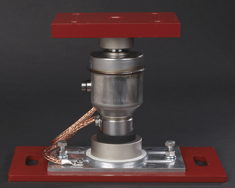
The analogue CPR and digital CPD models are said to have an unrivalled track record for reliability and performance. Both are based on the same mechanical envelope, and key design features are said to set these load-cells apart from competitive units (see fig. 1). The company’s engineers have not just focused on the design of the load-cells themselves, but also on the functionality of the mounting assembly. Key features include:
- The central column has a dedicated shape that incorporates top and bottom spherical surfaces.
- Proprietary heat treatment provides a robust yet highly repeatable central column.
- The design incorporates eight strain gauges, strategically placed to provide optimum performance even under adverse loading conditions.
- A compact special seal is incorporated in the bottom assembly to prevent dust/debris/water causing problems. This removes the need for more onerous covers, which can do more harm than good.
- The inside of the load-cell is protected from the environment by a fully weld-sealed two-part stainless steel outer housing. The bottom section is noticeably thicker than the top in order to provide mechanical protection to the load-cell.
- A glass-to-metal seal ensures IP68 sealing for the cable entry. The digital CPD has an external plug/socket to allow the cable to be removed. Braided, rodent-proof cable is available.
- The anti-rotation pin prevents the load-cell rotating in its mount, thereby eliminating possible cable damage.
- The insulation pad between the bottom mount assembly and the base plate minimizes damage due to electrical discharge. Braided copper cable electrically links the bottom of the mount assembly with the top plate, bypassing the load-cell.
Digital load-cells
Digital load-cells were first developed in the 1980s, initially to make low-cost, low-capacity load-cells in high volumes. The concept was based on the presumption that emerging low-cost electronics could be used to provide output compensation corrections for less-than-perfect load-cell designs.
It is only really over the past decade that their advantages have been fully utilized for high-capacity weighbridge load-cells, providing important and tangible benefits for both the manufacturer and the end-user. The Bilanciai Group have been granted two patents relating to the design and use of digital load-cells (US 7,151,230 B2 and US 7,361,851 B2). Each digital load-cell has on-board electronics which carry out a number of functions and supply a digital representation of the load on each load-cell. The load-cells at the heart of a weighbridge system form a communication network allowing direct access to the parameters of individual load-cells. The individual calibration data for each load-cell is stored in the electronic memory. Digital load-cells facilitate calibration and trouble-shooting.
Effects of ambient temperature changes on weighbridges
In some regions, ambient temperatures can easily change by more than 50°C from winter to summer. Steel weighbridge decks act as a huge heat sink and may reach temperatures approaching 80–90°C. There are two temperature-related factors to be considered which can affect performance.
First, the deck will expand and contract in three dimensions. An 18m deck will expand lengthways by approximately 0.2mm per degree change in temperature, meaning an unrestrained deck could change in length by around 16–18mm. The width will also change by approximately 3–4mm. Meanwhile, the relatively shaded concrete foundations will see a much smaller expansion. Overall, the relative expansion could be around 10–12mm. The effect of this longitudinal expansion will be to introduce angular loading to the load-cells, which could be in the region of 1.5 degrees (often known as cosine error). If the load-cells are not designed to accommodate this off-axis loading, weighing errors of several scale divisions can be introduced.
Secondly, temperature changes have an affect on the load-cell performance itself. High-quality load-cells are individually compensated for temperature effects on span and zero during manufacture, usually over the range from –10°C to +40°C. Lower-cost load-cells may well not have been individually tested and compensated, further adding to unwanted errors.