Capsule Pipelines For Aggregate Transport
By Jonathan Carter and Kevin Troyano-Cuturi, Department of Earth Science and Engineering, Imperial College, London
A survey of the methods used to transport aggregate, both within quarries and to deliver the product to customers, will identify four principle approaches. These are conveyor, truck, rail and barge, each of which comes with a different balance of capital costs, operating costs and operational flexibility. Which is most appropriate will depend on the exact conditions of the production process and it is very likely that several modes of transport will be used in the delivery chain. However, there does exist a fifth method – capsule pipelines, which, apparently, are used only in one limestone quarry in Japan.
Capsule pipelines
Capsule pipelines are small capsules, possibly with a set of wheels at either end, that can be propelled along a pipe. The idea of using such capsules to transport freight, and people, has been around for 200 years. The earliest proposal for moving goods in pipelines appears to have been by George Medhurst in about 1810. A practical application was created by Latimer Clark in 1856 with a pneumatic tube connecting the central station of the Electric Telegraph Company to the London Stock Exchange. This simple technology continues to be used worldwide to move small objects over short distances, such as moving cash between tills and a central office in a supermarket. The first wheeled capsules made their appearance in 1861 with a 30in pipe constructed by the Pneumatic Dispatch Company. The technology was found to be too expensive to operate and the system closed in 1874.
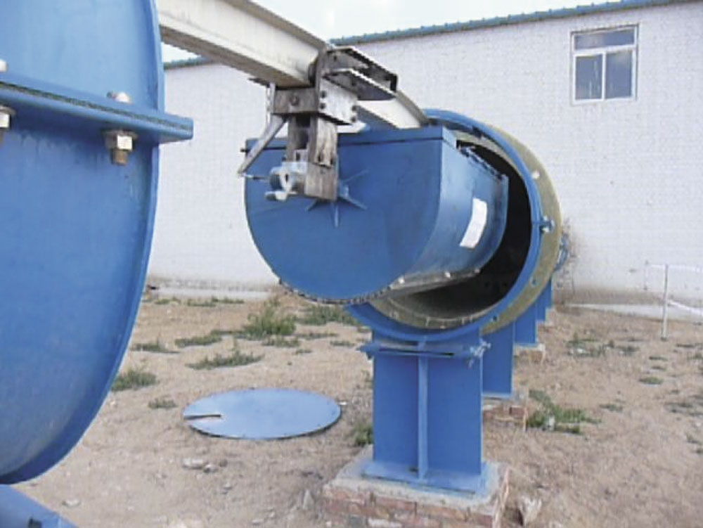
A new era for wheeled capsules began in the 1970s with the construction of two large-diameter pipe systems with wheeled capsules. In the US, Tubexpress Systems Inc. built and tested a 1,400ft long x 36in diameter pipe with 7ft capsules powered by compressed air. Figure 1 shows a prototype capsule being inspected by the system designer, Dr M.R. Carstens. However, the research did not produce a commercially attractive system and it was never installed in any quarry.
In the USSR, the Lilo-1 system (fig. 2) could transport 25 tonnes of sand and gravel at a time. The system used a 2.1km long pipe of 1,020 mm diameter within which six capsules formed a single train. Speeds of up to 50km/h were reported. A later system, Lilo-2, used an 8km pipe of 1.27m diameter to move 8 millions tonnes of sand and gravel per year. Both systems were powered by compressed air, but are now believed to be closed.
A test system constructed by BHRA at Cranfield in the 1970s comprised a 550m loop using a 600mm diameter pipe. The longest continuous test was some 7,500km, at the end of which the capsule was not in need of any essential maintenance. A report published by the British Technology Group, which examined why the technology had not been taken up, concluded that while many industries were prepared to consider pneumatic capsule pipelines, fears about the mechanical reliability of the system and unknown financial implications deterred any companies from implementing a pneumatic capsule pipeline system without first seeing a real working example.
The most successful applications of the technology have been in Japan. Sumitomo Metal Industries built a 3.2km pipe of 1m diameter in 1980 to transport limestone to a cement plant (fig. 3). The system transports over 2 million tonnes each year and has reportedly achieved an operation rate in excess of 95%. This system is still in operation today.
In 1997, the Florida Institute of Phosphate Research commissioned a demonstration project from Magplane Technology Inc. for a pipeline capsule system using linear synchronous motors for propulsion. The demonstration pipe was 275m in length and 610mm in diameter; each capsule could carry 300kg and achieved a peak speed of 18m/s (fig. 4.). The final report, published by Magplane Technology in March 2001, claimed that preliminary economic studies had shown a satisfactory return on capital. However, in its conclusions, the Florida Institute of Phosphate Research stated that much more testing was needed before the system could be considered as a candidate for commercial operation.
A different approach is now being applied by Magplane Technology Inc., who signed an agreement in May 2007 to provide a system for the transportation of coal in Inner Mongolia. Their new design is a development of the prototype built for the Florida Institute of Phosphate Research and continues to use linear synchronous motors, but the wheeled capsules have been replaced by an overhead monorail (fig. 5). It is expected that the final system will be able to transport 37 million tonnes per annum, and a 1km test loop capable of handling 5 million tonnes per year was due for completion in 2009.
All of the capsule pipelines that have been used, or designed, for the transport of aggregates have been of a similar configuration. A typical capsule has a central carrier for the aggregate with sets of wheels at each end. These wheels engage with the walls of the steel pipe and the capsule is propelled along the pipeline. Propulsion has generally been provided by compressed air, although linear synchronous motors have been tested.
New design concept
Imperial College has been reviewing the currently available technologies and is proposing a capsule pipeline that uses a different design methodology. The design utilizes tried and tested methods developed for the roller-coaster industry to deliver a capsule system with improved capabilities and robust economics.
In the pipelines described above, the pipe plays the key role in guiding the capsule. With Imperial College’s design, the capsule is guided by a steel track laid within the pipe. Therefore, the pipe primarily acts as a barrier to isolate the system. If the pipe is to be buried it will maintain the void space, and if it is on the surface it will act as a safety barrier. In both case it is possible to use polyethylene for the pipe material, which is significantly cheaper than the steel piping that has been used in other systems. The pipes can be placed wherever is most convenient. The cheapest option is likely to be to lay the pipe on an earth base with occasional concrete/steel supports. Alternatively, the pipe could be buried, which might be required by planning authorities, or suspended from pylons similar to a suspension bridge. In traditional rail systems the track is laid on separate sleepers, whereas with Imperial College’s system the track and sleepers are combined. This means that the track can be pressed from strip steel, which makes it easy and cheap to manufacture. Both the pipes and the track can be prefabricated and simply bolted together on site. When they are no longer needed they can be unbolted and moved to where they are needed next.
Figure 6 shows the preliminary design for a capsule. It is composed of two parts with a flexible bearing between the two. Both parts have four wheels, each of which uses a polyurethane tyre to prevent damage to the track and which has good wear characteristics. The two outer wheels transmit the weight of the capsule and ballast to the track, while the central pair, which are set to rotate horizontally, guide the capsule along the track. The capsules can be coupled together to form longer trains. The rotating coupling allows each capsule to be rotated so it can be emptied. The overall design allows the capsule to travel round curves with a radius of as little as 10m, as well as up very steep slopes. Modifications to the design could allow the capsule to negotiate even tighter curves or to travel vertically.
Propulsion is provided by linear induction motors (LIM) set in the base of the track. This type of propulsion has been used in a wide range of transport projects, such as roller-coasters, airport luggage-handling systems and aircraft launch systems for the navy. They are very energy-efficient and have no moving parts. As the capsule passes over a motor, an aluminium plate on the base of the capsule interacts with the electromagnetic field generated by the motor and the capsule is pushed forward. The absence of moving parts results in minimal failure rates, improved reliability and low maintenance costs.
Economics
The generic design described above can be scaled up and down to provide different system capacities. However, there is a minimum diameter of pipe that can be accessed for the occasional replacement of a LIM, which has been determined at 1,350mm. The maximum capacity of this minimum system would be 20 million tonnes per year. If higher capacities are needed a larger system could be designed, or two or more pipes could be used in parallel. To assess the economics, the costs of using trucks, conveyors and the capsule pipeline over distances of between 2km and 350km have been compared.
Example 1: 2km in quarry system
This example consists of a 1km uphill section followed by a 1km downhill section within the boundary of a quarry. This means that both the pipeline and the conveyor can be constructed on the surface.
The capsule pipeline is always more cost-effective than a conventional conveyor system. Compared to using trucks, the capsule pipeline will recover its capital costs once the total production exceeds 1.8 million tonnes.
Example 2: 36km cross-country route
The second example consists of 20km of level travel, an 8km uphill section and an 8km downhill section. It has been assumed that this system will be constructed in the UK and, hence, will need to be buried to comply with planning regulations. The trucks, meanwhile, are forced to follow the existing road system for a distance of 58.4km.
Again, the capsule pipeline is always more cost-effective than a conventional conveyor system. Compared with the use of trucks, the capsule pipeline will recover its capital costs once the total production exceeds 5 million tonnes.
Example 3: 350km haul over level ground
This final example was designed so that the trucks would be operating at their most efficient. It is assumed that the trucks can use a motorway for the whole journey and that both the conveyor and the pipeline would need to be buried.
The capital costs shown for the conveyor and the pipeline are for a system with a maximum capacity of 20 million tonnes per annum. If it is assumed that only a single pipeline is needed to deliver the required capacity, and if a suitable rail line is already available, it would be necessary to transport approximately 150 million tonnes before the capsule pipeline would be come more cost-effective. As before, however, the pipeline is more cost-effective than the conveyor, and if more than 12 million tonnes need to be transported the pipeline will be more cost-effective than using trucks.
Conclusion
It can be seen that a capsule pipeline would provide better economic value in many situations than the currently used options of conveyors and trucks. The proposed design draws heavily on the technology developed by the roller-coaster industry and has several practical advantages over the current approaches. The system can be buried, laid on the surface or suspended from pylons to form a bridge; it can also handle steep gradients and short-radius turns. The lack of moving parts and the high reliability of the LIM mean that the system will also have operational advantages.