Major Investment For John Wainwright & Co.
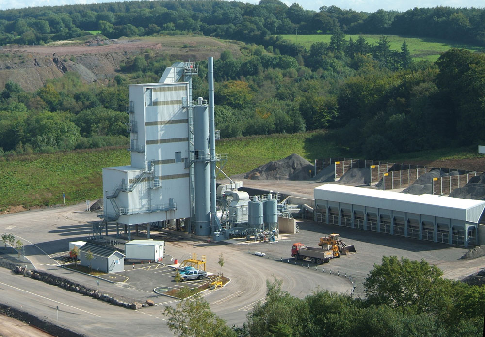
New Benninghoven coating plant for Moons Hill Quarry
Moons Hill Quarry, located on the Mendip Hills in Somerset, has been operated by John Wainwright since 1897 and is the only operational basalt quarry in the county and surrounding area. Coated materials have been produced at the site since 1910 when the first No.001 Ransom–verMehr coal-fired stone dryer was installed. The dried stone was discharged into a wheelbarrow and then mixed with tar by hand.
Over the intervening 96 years many different plants have graced the skyline of the quarry, which sits on the edge of the village of Stoke St Michael. The quarry has been the main employer in the village for most of the 20th century.
In early 2005 the decision was made to replace the 33-year-old Parker plant with one of the latest state-of-the-art plants, which would allow the company to satisfy future demand with improved levels of service.
To achieve the mix specifications, production targets and the necessary environmental criteria, a Benninghoven model TBA240U asphalt plant, equipped with a 4,000kg mixer, was selected. The plant has a production output of over 200 tonnes/h of dense basecourse at 4% initial moisture, and 120 tonnes/h of stone-mastic asphalt (SMA).
Designed to provide significant operational benefits and cost savings, the new plant is able to produce a wide range of high-specification coated materials, including modern thin surfacings, SMAs and other specialized mixes, and will allow Wainwright to provide a more comprehensive and efficient service to their main markets throughout their market area.
Before the development could commence, the entire 4.6-acre greenfield site had to be levelled and prepared. Thanks to careful forward planning and effective project management, the various civils were completed on schedule. Large-scale landscaping was also implemented both to level and shape the roadway systems and to create screening bunds in preparation for installation to begin in May 2005. In total, over 300,000 tonnes of material were removed to accommodate the new site.
The aggregate feed system consists of an inline unit of 11 cold-feed hoppers, each of 14m3 capacity and fitted with a frequency- controlled belt feeder for accurate blending of the aggregates. Four of the hoppers are for sand and are equipped with hopper-wall vibrators to ease material flow. All the hoppers are sheeted on their sides, ends and roofs, with an extended canopy over the sand hoppers. A full-length concrete retaining wall supports the feed ramp, while the bulk of the aggregates are stored in large covered storage bays holding approximately 2,000 tonnes of materials.
A 50m long collecting conveyor delivers material on to a 19.5m long x 650mm wide inclined dryer feed conveyor, which discharges on to a short 3.5m long reversible slinger conveyor from which material is fed directly into the dryer drum.
The aggregate dryer drum, which is 2.3m in diameter x 9m in length, is fully lagged with 70mm thick Rockwool insulation and aluminium clad for heat retention and noise reduction. The drum is friction-driven by four support rollers through individual 15kW geared motor units. The dryer is enclosed by a 2m high safety fence fitted with an electrical interlocked access gate.
The burner is a Benninghoven Rax-Jet 4-3EGOFU type, which burns both gas oil and natural gas. This is equipped with a full range of operating and safety devices to allow high-efficiency fuel usage. An air inlet silencer is connected to the burner to suppress noise levels. The burner and silencer are mounted on a track to allow the unit to slide back from the dryer for routine servicing. A new natural gas supply was installed for the plant at a cost of £290,000, which included the laying of a new 1.75-mile pipeline.
The plant’s dust-collection system, sized for the dryer unit and mixing section scavenging, is rated at 52,000Nm3/h and achieves emission levels of less than 25mg/m3. A primary skimmer unit mounted alongside the dryer separates any coarse dust from the airstream, which passes to the hot-stone elevator feed boot via a gravity flap valve and chute. A secondary cassette bag-filter system collects any remaining dust and transfers it, via two screw conveyors, to a filler elevator. Dust is also collected from nuisance points at the screen, weigh hoppers and elevator. A dust monitor mounted on the exhaust stack provides a remote read out in the operator’s cabin. As a result, the plant meets the most stringent dust-control regulations.
Any excess dust collected can be discharged from the reclaimed dust silo through a rotary valve into a twin-shaft paddle conditioner where water is introduced, thereby providing an environmentally friendly method of purging the reclaimed dust.
Hot aggregates are transported from the dryer up to the screen by a vertical bucket-type elevator. This is totally enclosed and features a heavy-duty double-strand chain and wear-resistant steel buckets with replaceable liner plates at impact points. Elevator drive is by a 37kW geared motor and toothed chain wheels at the elevator head. The elevator features externally located bearings and a safety backstop facility. A wide platform provides access for maintenance.
Material discharged from the elevator passes into a six-deck screen, which features twin-shaft drive via two19kW, ‘bolt-on’, low-maintenance vibrating motors. These drive units are mounted outside the screen housing to permit high-temperature screening of materials. Wide access doors together with a roll-away chute provide access to all screen decks. An extraction fan ensures negative pressure is maintained in the screen housing for optimum dust control.
The hot storage section consists of six bins and has a total capacity of 160 tonnes. All the bins are insulated and clad and each is fitted with a continuous level indicator and overflow chute. Discharge is by a pneumatically operated radial door, which accurately regulates material flow to the aggregate weigh hopper, from where the aggregates are discharged direct into the mixer. Accurate weighing of ingredients is achieved by separate load-cell-mounted weigh hoppers, comprising a 4,000kg capacity aggregate hopper, a 600kg filler hopper, and a 400-litre capacity weigh vessel for bitumen. A 1,400 litres/min injection pump forces the bitumen into the mixer. Mixing takes place in an insulated 4,000kg capacity, twin-shaft paddle mixer, with drive provided by two 55kW geared motor units through synchronized gears. A rapid and thorough mixing cycle is achieved by the mixer’s efficient paddle arrangement, while a radiation pyrometer is situated at the mixer discharge to indicate mix temperature.
Mixed material discharged from the mixer falls into a 4,000kg skip unit, which runs on horizontal tracks and distributes the material into six 60-tonne compartments, arranged in two rows of three, providing a total storage capacity of 360 tonnes. All are fitted with high-level warning indicators and are insulated and fitted with electric trace heating around the discharge doors. A direct load-out hopper is positioned beneath the mixer. All bins are mounted on load-cells to ensure accurate material loading.
Bitumen is stored adjacent to the plant in two 150m3 capacity and one 100m3 capacity vertical tanks; these are Benninghoven’s latest high thermal efficiency units, which give low running costs owing to their stepped heating system design. An in-built loading system with high-level probes offers fail-safe filling with no possibility of spillage.
Filler is stored in an external two-compartment vertical silo holding approximately 85m3 of reclaimed filler and 55m3 of imported filler. Both compartments are equipped with level indicators and shut-off valves.
A gravimetric additive system is also incorporated in the plant to feed granulated material from a 30m3 silo. Each batch of granulate is accurately weighed in a load-cell-mounted weigh hopper before being discharged through a butterfly valve to the mixer. A similar specification silo for pigment is sited alongside.
The plant is controlled by a Benninghoven Online Batcher 3000 computer system, which displays all plant functions via colour graphics. The system, which is housed in an air-conditioned and heated control cabin overlooking the plant, is modem linked and provides storage for up to 500 asphalt mix recipes.
All the equipment was supplied and installed to exacting requirements and in accordance with current CDM directives.
Acknowledgement
The editor wishes to thank Peter Barkwill, managing director, and Ian Timberlake, commercial director, John Wainwright & Co. Ltd, and Nigel Moreton of Benninghoven UK Ltd, for their help in preparing this report.