Point-Cloud Surveys and Geotechnical Assessments
First published in the April 2015 issue of Quarry Management
The beneficial impacts of modern point-cloud survey techniques on geotechnical assessments are brought into focus using a series of quarry case studies
By Adrian Wilkinson, geotechnical director, QuarryDesign
QuarryDesign have long been at the forefront of the UK quarrying industry for their use of modern surveying techniques to produce exceptionally high-quality rock-face and soil-slope surveys, and for their interrogation of those surveys using specialist software to allow a better understanding of the geological and geotechnical properties of a wide variety of industrial mineral and aggregate quarries.
Previous papers in QM introduced the relatively new (as then) technologies of long-range high-resolution LiDAR scanning (March 2011) and UAV-derived photogrammetric models (April 2014). Both survey techniques result in a point-cloud survey (a survey frequently comprising millions of points rather than the hundreds or thousands of survey points in a conventional survey).
Whilst the previous two papers introduced the technologies (and in the case of the April 2014 paper, the legalities of UAV use), this paper focuses a series of case studies where the use of these survey technologies and the subsequent interpretation has resulted in a benefit to the quarry concerned.
In addition to the obvious collection of ground survey data for slope stability calculations, these technologies have had a beneficial impact on the following fields of geotechnics:
- Rock-mass classification and quarry face stability assessments
- Rock-fall assessments and verification of efficacy of mitigation measures
- Rock-fall and failure monitoring.
The safety implication of using either or both of these two complementary remote surveying technologies was recognized in November 2013 at the MPA’s annual Health and Safety Awards conference, when QuarryDesign were awarded joint runner-up in the Engineering Initiatives category.
Review of point-cloud surveys
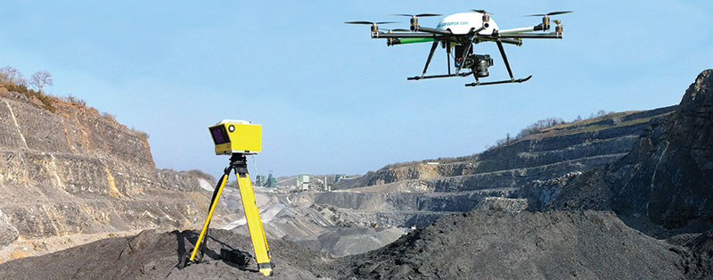
Both LiDAR (laser scanning) and photogrammetric (multiple overlapping photograph) surveys produce an initial result that is a point cloud. For topographical survey uses these point clouds can be subsequently post-processed to produce the more typical break-line and spot level surveys most quarry managers will be familiar with. Both systems can be used from the ground or mounted on aircraft. Increasingly, the aircraft-mounted options now utilize what are referred to variously as a UAV, UAS, sUAS, RPAS (unmanned aerial vehicle, unmanned aerial system, small unmanned aerial system, remote piloted aircraft system respectively), or simply a ‘drone’.
Photogrammetry relies on two or more (now frequently hundreds or even thousands) of overlapping photographs, some scaling or survey control, and a photogrammetric software package to produce a 3D model consisting of coloured points. These points can then be joined by triangles and rendered to make a solid mesh, as shown in figure 1.
LiDAR (Light Detection And Ranging) or laser scanning is similar to a traditional total station theodolite but makes multiple numerous ‘shots’ on a grid pattern. High-resolution long-range LiDAR scanners can take shots with micro-radian spacing. As well as flight time and shot bearing and angle (which is subsequently converted to an XYZ co-ordinate), many LiDAR scanners also record the percentage of light reflected back, measured as intensity, and can colour the point cloud from a calibrated digital camera (see QM, March 2011). In general, buildings and strong, bright rock types (un-weathered granites, limestones etc) produce high-reflectance (bright) points and vegetation and weak, dark rock types (shale, coal, clay, soil etc) produce low-reflectance (dark) points in the resultant point cloud. Software is available to also calculate the ‘inclination’ or orientation of points in the point cloud from the point normals. Similarly, software can calculate the ‘confidence’ of the reflected points based upon the angle of incidence at which the laser strikes the reflected surface, with a perpendicular reflection being high confidence (bright point) and a point reflected off a parallel or tangential feature being low confidence (dark points). This helps to ‘see’ into the dark shadows of the photograph (Red Green Blue/RGB) coloured point cloud.
Post-processing of LiDAR point clouds into ‘inclination’ helps the geotechnical engineer to more readily identify joint planes, and post-processing into ‘confidence’ shows more clearly the joint and block edges. Figure 2 shows an example of acquired and processed LiDAR point-cloud data by each of these four categories.
Rock-mass classification and face stability
Both photogrammetric- and LiDAR-derived point-cloud surveys have been used at numerous quarries throughout the UK to help the geotechnical engineer better understand the rock-mass characteristics (joint orientation and persistence, kinematical analyses and projection of potential failure planes).
As shown in figures 1 and 2, the two systems produce an exceptionally high-quality survey of the quarry faces and, being co-ordinated to the relevant Ordnance Grid and Datum, the joint sets and fracture orientations can be measured. The advantage of using point clouds to determine fracture orientation is that fractures out of reach of the geotechnical engineer can safely be measured in the office rather than by compass clinometer in the quarry (QM, March 2011), and can be carried out using automatic joint-detection software, such as Split-FX, or manually, as shown in figure 3. A second advantage is that a permanent record of the faces at the time the data were collected is retained and the author has found that, in many instances, the ability to cross-reference newer surveys with older surveys has been useful in building up a 4D picture of the changing geotechnical conditions (3D plus time as the fourth dimension), as demonstrated later in the section on monitoring.
As well as being able to measure the dip and dip direction of a joint plane, surveying software allows the extrapolation of an exposed joint plane upwards through previously excavated rock or back beyond the quarry boundary and downwards into rock still to be excavated. The extrapolation of a given joint plane downwards ensures that the geotechnical engineer/geologist producing the quarry design can predict and ameliorate against future potential planar or wedge failure (figs. 4 & 5). Extrapolation of joint data in this manner has also been used to determine the likely break-back distance for a historic (pre-Quarries Regulations) but still active large-scale wedge failure in Northern Ireland. In this instance the unstable land in the fields behind the quarry face, lying within the projection of two intersecting joint planes constituting the wedge failure zone, was accurately determined. This ensured that only the minimum land-take required for increased/additional perimeter safety was fenced by the operator.
Rock-fall assessments and verification of mitigation measure efficacy
As well as rock-mass geotechnical assessments, point-cloud surveys allow accurate rock-fall simulations (as long as correct rock-fall program material properties are adopted). These simulations can be used to assess the need for rock-fall protection and then to determine the type of rock-fall protection (face netting, rock-fall fence, rock-trap bunding etc), and can also be run after the installation of any mitigation measures to assess their efficacy.
QuarryDesign have been using both LiDAR- and UAV-derived point-cloud surveys in a wide range of rock-mass environments with the largest rock face currently surveyed being a 450m high x 500m wide sea cliff in Gibraltar for Golder Associates (using a UAV-mounted photogrammetric system).
The Quarries Regulations guidance for a rock-trap is one-quarter of the face height in width and one-eighth of the face height in height. This is largely based upon empirical results and generally works well for quarry faces of the height that modern quarrying practices adopt. In some cases, however, this empirically guided size can be overly conservative. In a recent situation in Northern Ireland an operator had historical (pre-Quarries Regulations) quarry faces up to 75m high. These were in a reef limestone with minimal bedding or jointing and exhibited no discernible remnant benches (potential launch features) to the eye from either above or below. Adopting the rock-trap guidance would have required a rock-trap 18.75m wide with a bund 8.75m high (taking up at least an additional 18.75m quarry floor width with 1:1 side walls) and, if constructed, would itself have been a significant structure. The total 37.5m easement effectively encompassed the whole of the quarry haul road, and until a specific rock-fall assessment had been undertaken the haul road had to be closed.
The assessment was complicated in that the quarry at this point is narrow, and as LiDAR is a line-of-sight technology, setting up on the quarry floor here and looking steeply upwards would have missed any remnant benches. Alternatively, looking down on to the faces from above would have meant the equipment and personnel having to set up right on the crest of the uppermost quarry face, which, obviously, was ruled out. It was considered that the only safe method of obtaining an accurate face survey, therefore, was with a UAV (although flying the UAV in the confines of this particular part of the quarry was not without some risk to the equipment, if not to the personnel).
The resultant model allowed accurate rock-fall assessments of these faces to be undertaken and the resulting mitigation measures for the highest face was a 2m high fence at an easement of 15m. The 15m easement captured all primary impact locations and the 2m high fence retained all potential secondary bounces and roll-out. The easement was specified with a dampening layer of fine aggregate to reduce secondary bounces and reduce the risk of single blocks shattering on impact with the quarry floor (the resultant fragment trajectories are outside the modelling capabilities of rock-fall simulation software). The resultant mitigation measures following the assessment were significantly less than the original appraisal indicated and have allowed the haul road to continue to be used (albeit with some minor re-adjustment).
The additional benefit of using high-quality point-cloud surveys (LiDAR or photogrammetric) is that the rock-fall simulation software gives an indication of impact energies and, thus, depending on the joint spacing and potential block size (which can be measured off the point-cloud survey), fencing of the correct strength can be stipulated. In another example, the strength of the back wall of a fitting shed was checked to ensure that it could withstand a rock-fall event in the designated danger zone (rock-trap) behind the shed without breaking through the back wall and potentially putting operatives working in the fitting shed at danger.
A particularly sensitive rock-fall assessment was undertaken for a Game of Thrones film set (located in a dormant quarry in Northern Ireland). In 2010, prior to the set being constructed, a geotechnical assessment of the face was undertaken. As with most quarry faces, once a kinematic mass failure of the rock mass had been ruled out, rock fall became the primary concern. The set was to be located against a 24m high basalt face and an initial terrestrial photogrammetric survey was created upon which to base a rock-fall assessment. As a result of that assessment (at the pre-planning stage) the set had to be altered to exclude an area of high rock-fall risk and the back of the set was widened, strengthened and, in effect, designed as a rock trap.
Since the set’s construction, the faces have been LiDAR scanned annually (fig. 6) and have been subjected to rock-fall assessments (fig. 7) and rock-fall monitoring. The results of the annual inspections and LiDAR monitoring have proven that all rock fall emanating from the face has been retained by the rock traps built into the back of the set.
Rock-mass and slope-failure monitoring
As introduced above, comparisons between successive LiDAR surveys, and to some extent photogrammetric point-cloud surveys, can be used to monitor rock fall, rock mass and slope failure. For centimetre-displacement monitoring LiDAR is the better technology, but for larger-scale movements (decimetre or meter displacements) photogrammetric surveys can be used. The advantage of both systems is that far more data points are monitored than with a total station and reflector, thereby producing a wider understanding of the nature of the movement. That is not to say that total station and reflector survey monitoring is inadequate, as this is by far the most accurate system, but rather that these relatively newer survey techniques provide additional data.
In the following case study (see fig. 8) the failure of a steeply inclined veneer of limestone at a quarry’s periphery failed when the soils behind it became oversaturated several years ago during a very wet winter. Quarterly monitoring by LiDAR from fixed survey stations has allowed the rates of movement to be calculated and it has been determined that with rates of movement moderating (less blue and red colours in the lower – more recent – image reflecting lesser amounts of erosion and accumulation thickness respectively), the failure may well be reaching equilibrium and be wholly contained within the easement to the site’s boundary.
Conclusion
Point-cloud surveys are invaluable in characterizing rock-mass failure potential and providing information on joints beyond the reach of the geotechnical engineer. The attitude of these joint planes can be projected back through the quarry boundary to assess any potential failure beyond the quarry and downwards to ensure that a safe, effective quarry design is adopted. The high level of detail offered by these types of surveys ensures that rock-fall assessments can be accurately undertaken, and that by comparing successive point-cloud surveys any rock fall can be monitored. In a similar manner, larger failures can be monitored and their movement rates assessed. Regardless of the technology used (terrestrial or aerial, photogrammetric or LiDAR), surveys of this kind can often be conducted from the safety of the quarry perimeter or even from the air, thereby significantly reducing the residence time of the surveyor and/or geotechnical engineer within the operational area of the quarry.
For further information and videos showing the manipulation of point-cloud surveys visit: www.quarrydesign.com
- Subscribe to Quarry Management, the monthly journal for the mineral products industry, to read articles before they appear on Agg-Net

