Limiting Blast-induced Damage On Final Pit Walls
Design methods for controlled blasts to limit final wall damage in quarries and hard rock mines
By A. J. Rorke, director, Blasting Technology, BME, a member of the Omnia Group, Johannesburg, South Africa
Wall failures are costly and often life-threatening. In some cases, a pit or quarry may close and ore/rock become un-mineable/unworkable. The geotechnical engineers at each operation are usually aware of pending wall failures, because some degree of warning is usually apparent, such as cracks opening up along the crest.
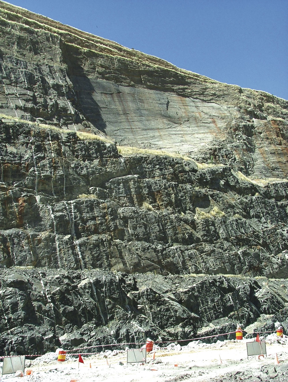
Failures are commonly associated with some form of structural weakness in the rock, such as a large, unfavourably orientated fault, bedding plane or joint plane. An example of this is shown in figure 1. Often, two intersecting joint planes form a wedge in the wall, allowing the material between to topple out (fig. 2). There are cases, usually in less-competent rock, where failure occurs along a curved surface that is created during the failure. This type of failure could also be associated with a dipping planar weakness, especially one that may be clay-filled and lubricated with water.
In all of these cases, blasting does have an impact on the probability and timing of failure, although the primary cause of failure is the presence of such structures. In cases where the rock structure is more favourably orientated, wall failures may not occur, but blast damage favours the planes of weakness. An example is shown in figure 3. This type of damage leads to dangerous highwalls, especially where access cannot be gained to remove loose boulders. However, it is avoidable with the correct design and application of blasting at the final pit wall. This paper presents some blasting methods for achieving better final walls.
TRIM BLASTING
The two areas that have the greatest impact on blast damage to the final wall are pre-splitting and trim blasting. Very often pre-splitting is not carried out in quarries, partly because of the cost, but mostly because the smaller-diameter holes and charges that are used in quarries tend not to be as damaging as larger-diameter blastholes. In many cases, however, back damage is still unacceptably high because of the structure or low strength of the rock mass.
Many operations treat the blasts next to the final wall no differently to other production blasts, but these blasts should be thought of as trim blasts and designed in such a way that blast energy into the final wall is minimized. A number of basic principles that can be applied to limit blast damage will be outlined in this paper, but first it is necessary to understand the mechanism of blast damage along final walls.
BLAST DAMAGE MECHANISMS
There are several possible mechanisms that need to be considered, these being damage due to gas energy penetration into pre-existing crack systems in the rock behind the blast, vibration-related damage and geometrical effects. These are briefly summarized below with one mechanism being rejected and two being explored in more detail, in association with blast design. In each case, the presence of rock structure within the final wall plays a pivotal role in the extent and nature of damage.
Damage by gas penetration
Originally it was believed that blast damage was caused mostly by explosion gases entering planar weaknesses in the rock and forcing them open. However, research work carried out by Brent and Smith (1999) illustrated that the pressures in the rock behind a blast, even as close as one burden, are negative and not positive. In other words, damage in the final wall is unlikely to be the result of gas pressure penetration into a pre-existing network of joints, bedding planes and faults.
Damage caused by high vibration amplitudes
At the same time, Rorke and Milev presented information on rock damage as a function of vibration amplitude. Their measurements indicated that fresh cracks (damage) in quartzite occurred at amplitudes above 650mm/s. Therefore, in this case, vibration amplitude can be considered as being a primary driver of rock damage. Methods to estimate and limit this potentially damaging source of energy are examined further in this paper.
Damage related to pit-wall and blast geometry
Very often pit-wall and blast geometry are ignored. However, they can be a major source of unwanted wall damage. The width, length and height of the trim blast have an impact. The angle of the faces along the final wall (pre-split plane angle if pre-splitting is being done) and whether double- or single-bench pre-splitting is applied will also influence the damage results.
Thus, during the design stages of the final pit geometry, decisions about the pre-split angles and pre-split heights should be made by considering the nature of blast-related damage that can occur as a result of poor choices.
CONTROLLING VIBRATION AMPLITUDE
The variables that affect vibration amplitude are:
- Hole diameter.
- Charge mass per delay.
- Firing delays and sequence of firing.
- Firing time accuracy.
- Level of confinement (burden).
- The presence or absence of air decks.
These factors can be applied to alter the predicted vibration generated by the back row of holes in a blast. Predicting near-field vibration requires a different attenuation model than the standard scaled-distance equation. In normal vibration prediction, the source (such as a blasthole or a blast) can be regarded as a single point source because it is far from the point of concern. However, close to blastholes, predicting vibration is a little more complex as each individual element of charge contributes to the vibration as a point charge.
BME’s Wall Control code uses Equation 2 (see footnote 2) to produce vibration contours around a column charge and thus allows an engineered design to the charge distribution in each hole. Assuming that rock damage will become unacceptable at a vibration amplitude of 1,000mm/s†3, the contours in the following charts (figs 4, 5 and 6) illustrate how a difference in the charge and stemming distribution in the back line of holes can have a very different effect.
In summary:
- Most damage is caused by a standard charge (fig. 4)
- In the case where the charge length is reduced to 3m in a 10m deep by 102mm diameter hole and the remainder of the hole is stemmed, little damage occurs in the top, but damage at the toe will still be extensive (fig. 5). This case also has the disadvantage that there will be limited breakage at the top of the bench and dangerous overhangs are likely to occur.
- The most favourable situation is where an air deck is introduced to distribute the charge energy from the short 3m charge almost to the top of the hole (fig. 6).
By using Equation 2, it is possible to work out the likely amplitude of vibration generated by a charge and thus decide on the ideal stand-off of a back-row hole from the desired pre-split and the charge mass, the charge length and stemming and air-deck lengths.
PIT WALL GEOMETRY
The angle of the final bench faces will affect the degree of damage caused by the adjacent blast. Equally, the height of the final benches will impact on the distribution of the damage. In all cases, geological structure has an important role in defining the extent of the back damage.
Angle of the pre-split
In a blast, there is an increasing degree of confinement towards the back rows of
the blast resulting in a more upward component of displacement than horizontal displacement. This is made more severe in multi-row blasts where inter-row delays are too short. When such a blast is taken along a vertical final bench face (fig. 7), a shear force is created along the pre-split (A) that rips the highwall apart along pre-existing planar weaknesses. This leads to an unstable final wall.
If the final face is angled, by blasting a pre-split at about 80° or shallower to the horizontal, the shear force along the final wall disappears and there is a much lower risk of geological planes of weakness†4 and sub-drill damage being torn open (fig. 8).
Geological planar weaknesses are most vulnerable to damage caused by shear forces if they are between horizontal and dipping into the final face. They are less vulnerable to damage if they dip away from the final wall into solid rock.
Double benching
The use of pre-split blasts that are double or triple the height of the production blasts is good practice as the confinement of overlying rock in the final wall helps to reduce the damage caused by the shear force described above.
This is illustrated in figure 9 and applies whether a pre-split has been drilled or not.
In the case where single-bench pre-splits have to be drilled because of drill limitations, the offset between pre-splits should be kept as small was possible†5 to limit the extent of crest damage, but adequate safety/catchment berms should be introduced at regular intervals.
THE VALUE OF ELECTRONIC DETONATORS IN FINAL WALL CONTROL
Buffer-row timing
Timing of the back rows is critical to ensure that damage is not caused by these holes firing too early and thus increasing confinement in the back of the blast. Because the spacing between the buffer holes differs from the pattern burden or spacing, the design of the connections between holes using fixed shock-tube delays is complicated. Many errors are made in both the timing design and the application of the timing in the field because of this complexity. The complexity that is required can be seen in figure 10. Often the blaster is left on his own to carry out the critical timing of the trim blast with no real knowledge of the impact of his decisions on the final wall. Complex trim blasts that occur along a curved final wall are even more difficult to time correctly with fixed-delay initiation systems.
The guiding principle in trim-blast timing designs is that the holes closest to the pre-split should be given the largest breakage angle. To achieve this large breakage angle, the holes must fire in sequence and later than the adjacent holes, ie the timing of the buffer holes needs to be specifically designed so that the timing contours meet the pre-split line at an acute angle of less than 45°, as illustrated in figure 11.
Electronic detonators allow controlled flexibility of the timing to ensure that the trim-blast timing happens according to design. Optimal blast-timing designs should be done by an engineer on a computer using software such as BME’s BlastMap code. This timing is transferred to the system blasting box and the detonators fire according to a design, thus bypassing potential creative input from inexperienced or unknowledgeable blasters.
Accuracy
Electronic detonators also offer a second benefit – accuracy. Electronic detonators will fire at their design firing times, whereas shock-tube detonator systems fire within a wide range of the design firing time, thus resulting in a high likelihood of non-sequential firing and driving up confinement and risk of damage along the final wall.
Vibration engineering
Precise detonators are defined as units that fire with a scatter in a firing time of 1ms or less. This means that wave interactions for holes with precise firing times occur in a predictable fashion, provided certain simplifications are considered.
Destructive interference can be achieved by choosing timing delays so that waves meet each other out of phase, and amplitudes are thus reduced. There is a risk, however, that constructive interference can occur if the wrong delays are chosen. Figure 12 shows simple sinusoidal curves that are used to illustrate the effect of different timing delays leading to destructive or constructive interference.
The illustration in figure 12 is greatly simplified, because it considers only two waves, both emanating from the same point in space. In blasting, the situation is significantly more difficult because the vibration waves generated by blastholes are complex and blastholes are separated in space by varying rock structure, thus resulting in different interference behaviour at different places around a blast.
If a single blasthole is considered, on detonation a shock wave radiates from it that turns into an elastic compression wave front that travels at a velocity controlled by the rock properties. For example, a brittle hard quartzite will transmit a compression wave at about 6,000m/s, whereas weathered shale may transmit a compression wave at about 3,500m/s. This wave front travels out through the rock from the detonating blasthole approximately as a sphere. Where it intersects a two-dimensional surface, such as the earth’s surface, it will appear as a circle, as illustrated in figure 13.
For different rock properties, distances between holes, the number of holes and the timing design of the blasts etc, the wave fronts emitted by each hole will combine together to form a pattern of circles that is referred to as an interference pattern. An example is given in figure 14.
Electronic detonators provide precise initiation, which means that the interference patterns generated from a blast are predictable and repeatable. This is not the case with pyrotechnic initiation systems (eg shock tube), where firing times vary over a range that is large enough to scatter the wave fronts and create a random and unpredictable interference pattern. Therefore, the advantage of precise firing times is that delays can be chosen so that:
- Destructive interference occurs between waves towards a final wall.
- Wave-front concentrations can be directed away from a final wall.
The risk with precise detonators is that concentrations of energy do occur along certain directions, and if these are not taken into consideration, blast vibration may actually be amplified.
An example is shown in figure 15 where the distance between holes and the precise delay times that were applied show a concentration in vibration in certain directions and a dispersion of wave fronts in other directions. To limit vibration, a dispersion of wave fronts is desirable.
CONCLUSIONS
This paper has presented a number of methods for producing good-quality highwalls. These include:
- Controlling damage by limiting intense vibration amplitude from individual holes along a final wall.
- Controlling damage by designing pit-wall geometries that are more robust to blasting along the final wall.
- Controlling damage by using accurate electronic delay detonators to prevent non-sequential firing in production blasts and focusing vibration energy away from final walls.
The methods that have been described are practical and easy to apply, provided some planning and forethought is given to each final wall or trim blast.
BIBLIOGRAPHY
- BRENT, G.F., and G.E. SMITH: ‘The detection of blast damage by borehole pressure measurement’, Fragblast 6, 1999, Johannesburg, South African Institute of Mining and Metallurgy, pp 9-13.
- RORKE, A.J. and A.M. MILEV: ‘Near field vibration monitoring and associated rock damage’, Fragblast 6, Johannesburg, South African Institute of Mining and Metallurgy, pp 19-22.
- HOLMBERG, R., and P-A. PERSSON: ‘The Swedish approach to contour blasting’, Proceedings of the 4th Conference on Explosives and Blasting Technique, 1978, SEE, pp 113-127.
This paper was presented at the March 2010 annual conference of the Institute of Quarrying Southern Africa and is published here by kind permission.