Load Control
Precision monitoring, profiling and control of motor loads on batch mixers and other process machinery
Monitoring the load on an electric motor that drives a machine or process can provide valuable performance information, as the motor will reflect directly the changes that are taking place in the process. With a mixer or agitator, for example, as the viscosity increases, more power will be required to stir the mixture, and the sensor output can be used to control the process, add materials, change feed rates, stop the machine etc.
A power sensor can measure these motor load changes and send a signal to meters, computers, programmable controllers, recorders or data-collection systems. Power sensors can monitor pump or fan flow, sense the beginning or end of a process, control optimum feed rate and sense an overload or loss of load.
The control of many process machines, such as grinders, mills, mixers, rollers, pumps, compressors, conveyers etc, can be improved dramatically by sensing true power instead of current. In practice, it does not matter how sophisticated the computer control system is, its overall performance will be largely dependant on the sensors at the front end.
ELECTRICITY, MOTORS AND POWER
Nearly all industrial motors are three-phase induction motors. The three-phase power creates a rotating field in the stator which ‘induces’ the rotor to rotate.
To measure three-phase power: P=(E)(I)(Cosø)(1.73), where:
• P = power (watts)
• I = current in each phase (amps)
• E = voltage phase to phase (volts)
• Cosø = power factor (ranges from 0–1)
• 1.73 = multiplication factor for three phases = √3
• 1hp = 746 watts
What is power factor?
With an induction motor, the current always lags the voltage. Power factor is the cosine of this angular lag. For a lightly loaded motor the power factor can be as low as 0.1. A power factor this low can be regarded as electrical inefficiency; current is flowing to the motor but is not doing useful work (power). As the load increases, the power factor improves and is typically 0.9 for a fully loaded motor.
Why monitor power instead of amps?
With increasing load on a motor the power factor improves rapidly but the current does not change significantly until the motor reaches about 50% of capacity.
- Power is linear; a change in load is a change in power (hp or kW).
- It provides the signal needed for machine or process monitoring and control.
- When the load is low, power is low.
- When the load is high, power is high.
- At light loads, power is 10 times more sensitive than amps.
When using a clamp-on ammeter on a motor reading 50% of full-load amps, the power sensor will be reading only about 10% of full load. Why is this? From the curves shown in figure 1 it can be seen that, for a lightly loaded motor, the current is high. Why? The power factor is low. As the load on the motor increases, the power factor increases, but the current does not change much.
This is the advantage of sensing power rather than amps. When the load is low, the power is low. When the load is high, the power is high. In practice, the result is that measuring power is sensitive through the whole operating range (0–100%) of motor load, making the control signal far more sensitive and useful to control a process. At low power factors, measuring current is insensitive and less suitable for process control.
PROFILING A PROCESS
One of the best applications for a power sensor is for monitoring viscosity changes in mixers and agitators. As a batch is processed, the power changes will reflect the viscosity changes and a good batch will fit the normal ‘profile’ for that product. The curves in figure 2 show a typical example from a two-speed, high-shear mixer. The five steps of this process are clear to see:
- dry components are mixed at high speed
- liquid is added at slow speed
- mixing continues at low speed and the power/viscosity increases to the desired level
- high-speed mixing begins and power increases sharply
- as soon as the power/viscosity begins to decrease, the batch is done.
It is noticeable that for the three batches run, the curves do not vary much. Any deviation from this profile should raise a red flag. Also, since power is linear with load changes, it is easy to interpret and extrapolate the results at both the low end and the high end.
Obviously, in different applications with different mixes the shape of the power curves will vary, but the technique makes it easy to compare good and bad batches and, thus, maintain consistent quality control.
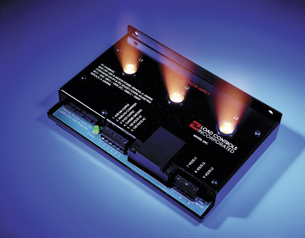
UNIVERSAL POWER CELL
Not all power sensors are made the same, however, and consideration needs to be given to a number of factors to ensure that a usable, repeatable control signal is sent to the controlling instrument or computer. Conventional CT (current transformer) based power sensors are not suitable when variable- speed drives or inverters are in use and will, if utilized, produce gross power errors (and thus load errors) due to limitations in bandwidth and sensitivity.
Power sensors that use current transformers perform badly where the three-phase supply is poor quality, non-sinusoidal or a variable-speed drive or inverter is used. One solution to this is the Universal Power Cell (UPC), which is specifically designed to cope with the most difficult industrial applications, including situations where inverter drives are used.
The UPC uses three balanced Hall-effect semiconductor devices that have the following two characteristics:
- They sense a magnetic field. When a current-carrying conductor passes through a magnetic flux concentrator and the Hall-effect sensor is placed in a gap in the concentrator, the signal is proportional to the current.
- The Hall-effect semiconductor can multiply two signals and is excited with a signal that comes from the voltage sample for that phase. The Hall device multiplies these two signals and the resulting output is proportional to power (volts x amps). This is an instantaneous vector multiplication which also calculates the lag or lead of the current (power factor). The signals for each of the three phases is summed and the analogue output signal is proportional to the three-phase power (hp or kW).
Using Hall-effect devices instead of traditional current transformers and voltage transformers greatly simplifies installation and offers considerable savings on installation costs.
Accuracy is also improved by eliminating the phase-shift errors from CTs and PTs, which can be large at low power factors. The Hall devices will also work efficiently on the output of variable-frequency drives. The analogue output can be connected to meters, computers, programmable controllers, chart recorders and data-loggers. It can also be used together with a ‘V’ series load-control unit if trip points and relay outputs are required.
Changing capacity in power cells
The gain or amplification for each of the three Hall devices is set with resistors. In the latest version of the UPC, the gain (which sets the value of the full scale capacity) is changed with a coarse and fine potentiometer adjustment. With an ohmmeter on two test points, the scale is conveniently arranged so that 5Kohms = 5hp, 10Kohms = 10hp etc. Thus, if the full scale is set at 100 Kohms (100hp), when the 4–20 milliamp scale reaches 20mA, 100hp is going to the motor. With the UPC, it is easy to change capacity to match the load without the hassle of rewiring current transformers. This provides maximum sensitivity.
THE SENSOR
A UPC works very well for process monitoring. It has both a 4–20mA and 0–10V analogue output (powered by the unit) which can be sent to:
- local and remote load meters
- data-collection systems
- programmable controllers
- chart recorders.
A built-in response adjustment allows for the smoothing out of the signal, especially when working with lumpy materials or slow agitators where the instantaneous or harmonic changes are usually not of interest.
The capacity or ‘full scale’ is easily changed to match the load. A lot of processing equipment is oversized, so by reducing the sensor capacity to match the actual load, sensitivity will be improved.
SIMPLE INSTALLATION
The self-contained Universal Power Cell is located in the control cabinet, which means:
- no holes in the tank
- no moisture or wash down problems
- no current and voltage transformers to complicate the installation
- the convenience of one model to cover a wide variety of applications.
OTHER APPLICATIONS
Processing facilities are now using these unique power sensors to monitor many other functions in their plant, including: pumps (flow rate, loss of load, bearing failure etc); fans (correct flow rates); grinders and pulverizers (maximize throughput); clarifiers (avoiding blockages); and energy input.
CONCRETE BLOCK PRODUCTION
A typical project set out to monitor a number of key motors in a concrete building block production plant with a broad range of motor-driven process machines, including crushers, mixers, fans and blowers. Use of the Universal Power Cell sensor proved to be ideal for process control and monitoring, resulting in product quality improvements and cycle time reductions.
Also, the project provided unexpected benefits by detecting bearing damage on a waste-crushing/recycling unit. Catastrophic failure was prevented and substantial maintenance cost savings were made.
Hall-effect power cells were fitted to some of the drives so that real-time recordings of electrical power could be made using the site data-acquisition system. The precise electrical power measurements proved to be extremely valuable.
Also, in the main mixer a number of dry materials are mixed with fly ash and water to produce a slurry which is subsequently cast into a mold. The mixing process had been the subject of problems where batches of material had been mixed for too long and had set in the vessel. Analysis of the power absorbed by the mixer motor showed that a good relationship existed between this and the mixture viscosity. The controlling PLC software was then modified to incorporate mixing to a viscosity end-point, derived from the stirrer power. Batch mixing is now achieved in a more consistent manner and maintenance and cleaning tasks are reduced.
Another part of the process being monitored was the recycling plant where waste block material is crushed, fed to a hopper and then blown to a storage silo under the control of a rotary valve. Various attempts had been made to automatically control the blowing of the powder using in-line flow monitors, but these had proved sensitive to jamming.
Analysis of the power traces from the sensor on the blower motor showed a relationship between power and flow rate which allowed the controlling loop to blow at constant power. Constant flow control was thus implemented using a UPC non-invasive sensor which carried no maintenance overhead.
Another control task for the Universal Power Cell involved automation of the pumping of slurry in the waste-recycling plant.